Section Four - Experimental Design
Author: Eric Schneider · 2026a-eric-schneider Node: Genspace NYC Affiliation: BioArt Studio, MakerSpace Charlotte
Form Prompt
Create a detailed experimental plan for your final project. Include a timeline for each part of your experimental plan (i.e., how long you would expect each step in your final project to take). (min. 15 lines/sentences — a numbered list is acceptable). Include specific methods/tools/technologies/biological concepts for each part of the final project and analysis. For each experiment and/or analysis, include a description of your expected results. If possible, include figure(s) that visually shows a broad workflow of your project or a specific aspect of your experimental plan.
Opening
The BioLight experimental plan follows a Design → Build → Test → Analyze framework — organized across three HTGAA aim phases: Aim 1 — Design & Build (Experimental), which establishes the biological construct and the Photoplasm hardware platform; Aim 2 — Test & Analyze (Development), which executes the full seven-stage wet-lab protocol from transformation through calibrated image exposure and bacterial H&D curve generation; and Aim 3 — Learn & Refine (Visionary), which extends the platform into open-source community distribution and cell-free biomanufacturing at scale.
The design phase of Aim 1 is essentially complete: BioLightV5 has been assembled in Benchling, validated through Asimov Kernel circuit logic, modeled in AlphaFold and ChimeraX, and ordered as a clonal gene from Twist Biosciences. The hardware build is running in parallel at my design studio and MakerSpace Charlotte — all Photoplasm physical parts are designed in Fusion 360 and printed in PETG on a Bambu X1 Carbon, with a full parts guide found in the Supplemental Information section.
All wet-lab work is conducted at Genspace (Brooklyn, NY), my assigned HTGAA Node and certified BSL-1 wetlab partner for this project. A complete fallback plan using pDawn-sfGFP (Addgene #107741) is documented and ready to activate if BioLightV5 sequence verification fails or exposure produces no usable bacteriograph after multiple attempts.
What you will find in this section:
Part A — Detailed Experimental Plan — a 17-step numbered timeline organized across the Aim 1 Design & Build and Aim 2 Test & Analyze phases, including the full Aim 2 — Test & Analyze (Development) seven-stage protocol (verify → transform → plate → expose → develop → calibrate → print) and the Minimum Viable Functional Validation (MVFV) blue light induction test that gates entry into image exposure work
Part B — Techniques Checklist — 19 techniques checked from the HTGAA form list, each annotated with its role in the project
Part C — Protocol Design — the single Aim 2 — Test & Analyze (Development) protocol, comprising two sequential blue light tests: a simple test-tube induction validation confirming construct function post-transformation, followed by full Photoplasm step-wedge calibration
Part D — Industry Council Companies — three primary partners each with a specific project role across the three aims, plus supporting partners
Part E — Workflow Figures — visual illustrations of the Aim 2 protocol and the BioLightV5 non-linear design network
Appendix — Standalone markdown protocol documents written for direct bench use at Genspace
The full step-by-step protocols are maintained as standalone documents and referenced throughout; what follows is the high-level experimental plan.
 *Gannt chart: Aim 1, Aim 2, Aim 3 - 5/19/2026
Part A — Detailed Experimental Plan
All initial dates are anchored to Twist BioLightV5 delivery on or before May 27, 2026, and Genspace Safety Training and Orientation on May 28, 2026 — a fixed date independent of Twist delivery status. Actual dates may shift based on confirmed order and delivery; the structure and format of the protocol remains intact.
Aim 1A — Design & Build (Experimental) · Design
1. BioLightV5 plasmid design in Benchling (complete, ~3 weeks elapsed) Asimov Kernel circuit logic → Benchling sequence assembly (pUC19 backbone, RsLOV–LexA408 fusion, sfGFP reporter, pColE408 operator, SD17 RBS, two distinct terminator sequences) → AlphaFold structural prediction → ChimeraX visualization of dark-state PDB 4HJ4 dimer and light-state monomer. Expected result: passing all four Benchling quality checks before Twist submission.
2. Twist Biosciences clonal gene order placed (order pending) BioLightV5 submitted as a single clonal gene under the 5 kbp synthesis limit. Target delivery on or before May 27, 2026.
Expected result: lyophilized DNA aliquot with full sequence verification report.
3. pDawn-sfGFP control ordered from Addgene (Order pending) Addgene #107741 (Riedel-Kruse Lab, PNAS 2018) ordered as bacterial stab. Ready-to-use fallback if BioLightV5 sequence fails.
Expected result: A viable living-cell bacterial transformation of BioLightV5, ready for use in Photoplasm device experiments.
See Section Two - Aims for illustrated pipeline
Aim 1B — Design & Build (Experimental) · Build
- Photoplasm device prototype: Fabrication & Documentation (Aim 1B completing by May 27)
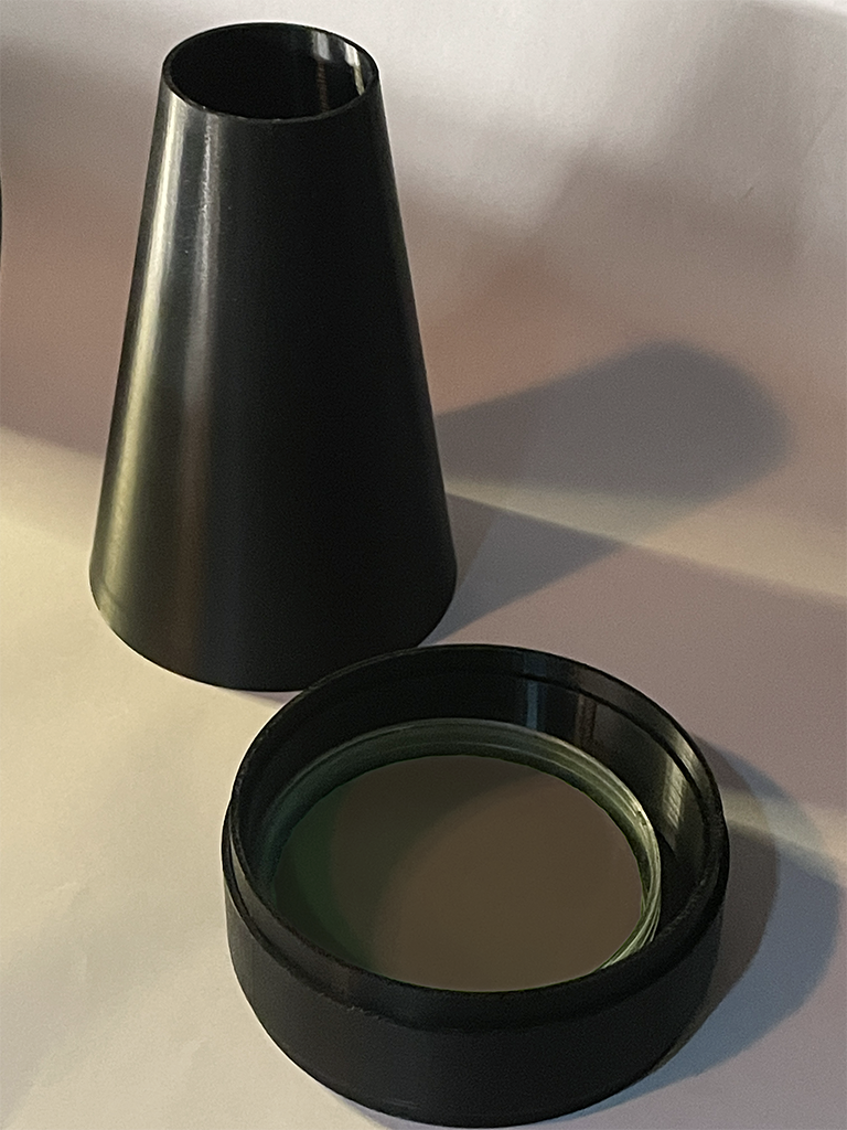
3D-Printed Modular Components designed in Fusion 360 and printed in PETG on Bambu X1 Carbon at my design studio and MakerSpace Charlotte. Parts include: dark chamber frustum cone (150 mm height, 51 mm ID top, 150 mm OD base), stackable spacer rings (~100 mm each, adjusting throw distance 6–12 inches), LED light Ring mount, OLED digital image carrier, bacterial plate holder, and plate heater with heat sensor. Electronics: Raspberry Pi 5, 470 nm LED light ring, PWM/MOSFET driver (IRLZ44N, GPIO18 control), light collimator, OLED digital image mask for variable density projection, focusing lens, AS7341 spectral sensor, Raspberry Pi Camera Module.
Expected result: a calibrated, light-tight imaging platform with documented optical stack. Full build sequece documented in Photoplasm Quick Start Guide
Aim 2 — Test & Analyze (Development)
The Aim 2 protocol begins on Twist plasmid receipt and Genspace orientation. Two blue light tests gate the path from transformation to image exposure: first a simple test-tube MVFV induction validation, then full Photoplasm step-wedge calibration. All wet-lab work is conducted under Genspace BSL-1 protocols only.
5. Genspace Safety Training and Orientation — Lab Block A (May 28, fixed, ~6 hours) Site orientation, BSL-1 safety review, materials check-in, equipment familiarization, lab notebook initialization. Proceeds regardless of Twist delivery status. Expected result: cleared to begin wet-lab work May 29.
6. P1 — Verify: plasmid receipt and gel verification (May 29, ~2 hours) Resuspend Twist DNA aliquot, confirm sequence report, run confirmation gel. Expected result: clean band, sequence-verified BioLightV5 ready for transformation.
7. P2 — Transform: DH5α transformation (May 29–30, ~2.5 hours active + 16 h overnight) Heat-shock transformation of DH5α competent cells with BioLightV5, recovery in SOC, plate on LB+Amp. All handling under red safelight to prevent leaky expression. Expected result: 10+ AmpR colonies after 16 h at 37°C in darkness.
8. P3 — Plate: colony picking, miniprep, and stock banking (May 30 – June 1, ~4 hours active + 16 h overnight culture) Pick colonies, grow overnight in LB+Amp in darkness, miniprep, glycerol stock banking at −80°C. Expected result: at least one sequence-verified working stock.
9. Blue Light Test 1 — Minimum Viable Functional Validation (MVFV) (June 1, ~2 hours — critical gate P3.6-G) Two culture tubes prepared from verified stock: one exposed to bench-top 470 nm source, one held in darkness. sfGFP emission confirmed visually. No Photoplasm device required — intentionally minimal, confirming construct function independently of hardware. This is the primary go/no-go gate for Aim 2 — Test & Analyze (Development) image exposure work. Expected result: measurable fluorescence in light tube, minimal signal in dark control. Failure triggers pDawn-sfGFP backup protocol; the June 2–21 hold window provides recovery time.
10. Hold window — device pre-work and sequencing convergence (June 2–21, ~3 weeks) Verified glycerol stocks held at −80°C. Photoplasm device pre-work completes: Cree LED irradiance gate cleared (≥100 µW/cm² at substrate plane), 16-step Bayer dither step-wedge calibration run, minimum effective dose (MED) and exposure window established. Expected result: device validated, exposure parameters locked, working stock confirmed and ready for Lab Block B.
11. Genspace Lab Block B — P4: agarose slab casting (June 22, ~3 hours active + 16 h pre-incubation)
Following Aim2_Protocol_AgaroseSlab.md: measure overnight OD₆₀₀, temper low-melt agarose to 42–45°C, mix cells into molten agarose, cast thin uniform slab in 90 mm dish, pre-incubate in darkness.
Expected result: uniform photosensitive substrate analogous to a silver-halide-in-gelatin emulsion.
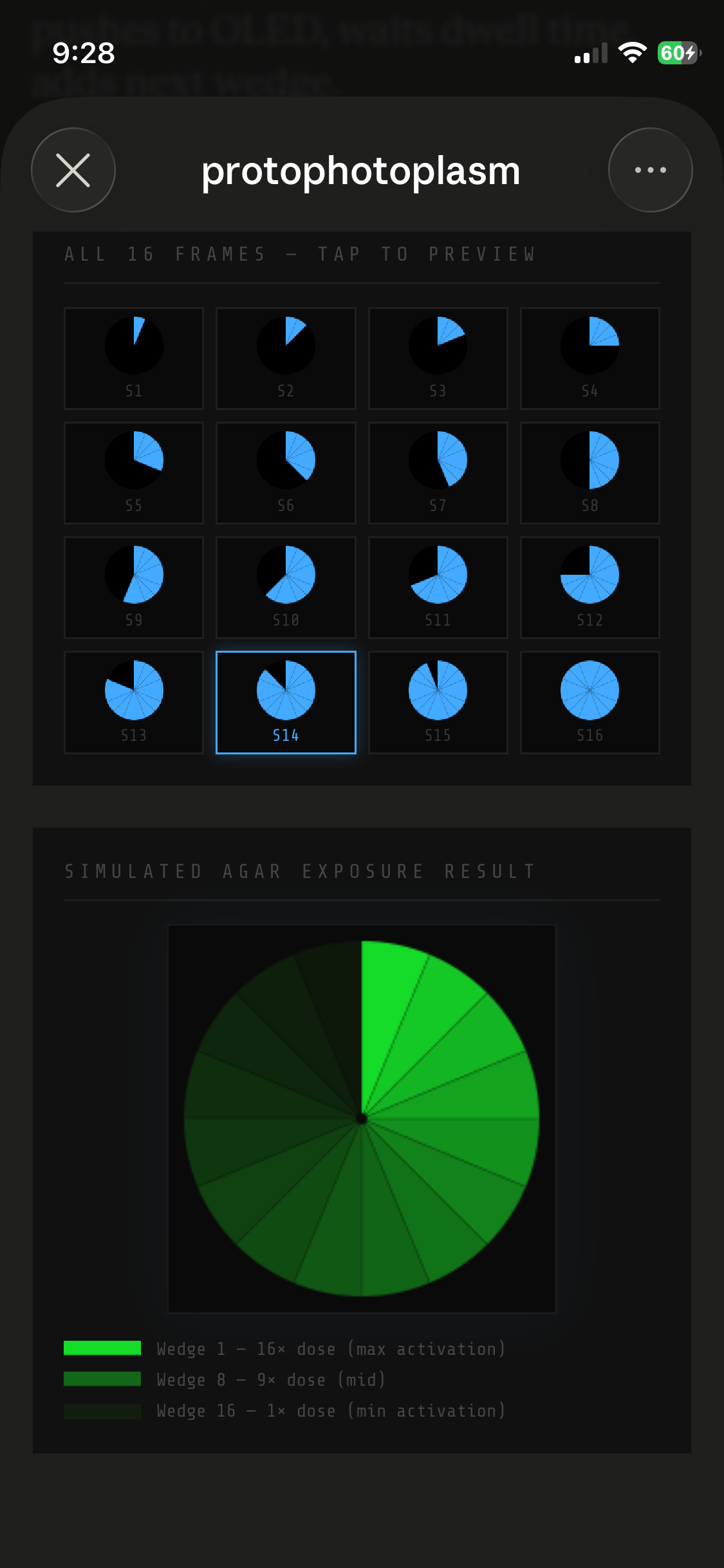
12. Blue Light Test 2 — P5: Photoplasm step-wedge calibration and image exposure (June 23, ~0.5 hours active + 4–8 hours exposure) With construct function confirmed by MVFV, the full Photoplasm device is engaged.
Visual Guide to Calibration Cycles
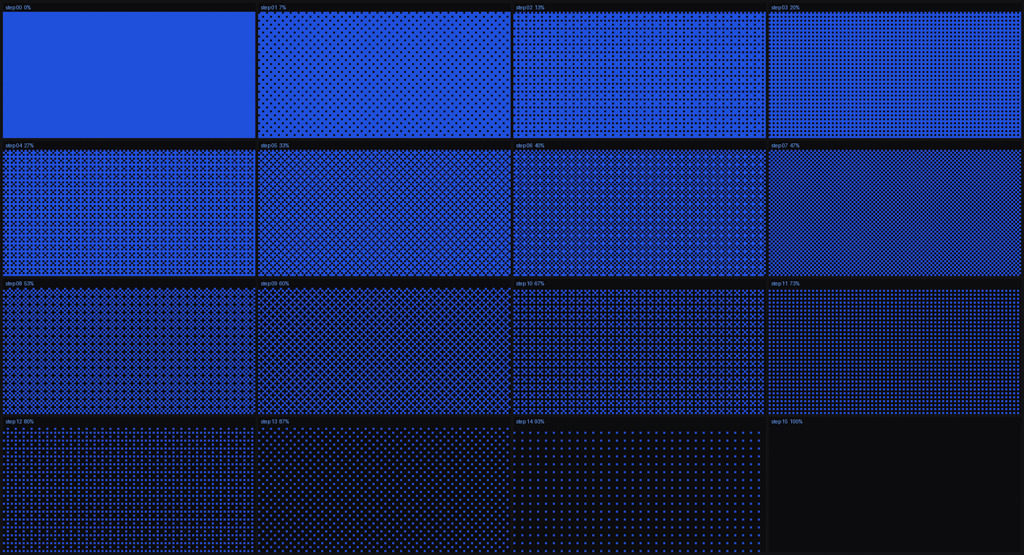 Project 16-step Bayer dither calibration target through OLED digital image mask at calibrated 470 nm irradiance and predicted F/8 aperture setting, to establish wavelength and illumination values.
 Insert agarose slab with bacterial lawn into plate holder and place under dark chamber
 Start timed exposure duty cycle dosing — dark growth, blue light dose, dark recovery, repeat — prevents over-expression and metabolic exhaustion across the 24-hour exposure window.
Three planned experimental exposures:
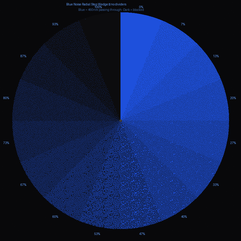 (a) Circular step-wedge for calibrating to H&D curve
 (b) Siemens Star Pattern for resolution and focus test measurement.
 (c) One original continuous tone image mask for the 12-piece Photoplasm Art Gallery series.
Experimental Aim: Raspberry Pi Camera Module provides real-time machine vision feedback during each duty cycle, feeding image data into a self-correction algorithm that adjusts subsequent dose parameters based on observed expression response.
Expected result: spatially patterned sfGFP expression confirmed at exposure completion.
13. P6 — Develop: post-exposure incubation and imaging (June 23–25, ~3 hours active + 4–16 h development) Post-exposure incubation in darkness at 37°C to allow sfGFP expression. Image under 470 nm transilluminator with 515 nm long-pass filter; AS7341 sensor captures fluorescence across 510–530 nm sfGFP emission window. Photograph plates for archival record. Expected result: measurable bacteriograph with spatially resolved sfGFP intensity gradient.
14. P7 — Calibrate & Print: bacterial H&D curve generation (June 25, ~4 hours analysis) Export AS7341 time-series CSV. Plot fluorescence vs. logarithmic light exposure for the step-wedge. Document toe, linear, and shoulder regions following Zone System sensitometric conventions. Expected result: a calibrated bacterial H&D curve — the central Aim 2 — Test & Analyze (Development) deliverable — characterizing BioLightV5 as a photographic substrate.
Aim 2 → Aim 3 — Learn & Refine (Visionary) handoff
15. Documentation, open-source release, and Aim 3 handoff (ongoing) GitHub Repository for Photoplasm to be published with all four protocols, hardware specifications, device firmware, Photoplasm Art Gallery exhibition framework, and observational data schema in the style of Transfyre.ai. My instructional design methodology includes experiential learning activities. Repository to be released under MIT open-source license via GitHub repository.
Genspace Community Project ↔ MakerSpace Charlotte collaborative build workshop scheduled as the Aim 3 distribution proof-of-concept. Machine vision self-correction data archive to be created as the foundational training dataset for the Aim 3 fleet-level neural network. Expected result: fully documented open-source platform ready for community replication.
At this time of this submittal, there are several HTGAA2026 colleagues interested in participating in a global expansion of the Photoplasm device initiative, as a cohort and individually. This is a very exciting prospect to demonstate the open-source and open-innovation pipeline, with a concept of a museum-grade “Photoplasm Art Exhibition” of experimental image exposures. A show that can be printed as fine art and travel the globe , with an online and printed publication. (5/23/26)
Decision Points and Fallbacks
- MVFV gate (step 9, June 1): Failure triggers pDawn backup protocol; June 2–21 hold window provides recovery — pDawn timeline (~10–17 days from trigger) converges into Lab Block B if started by June 5.
- Cree irradiance gate (by June 22): If ≥100 µW/cm² not achieved, fallback blue-light rig engages — uniform 470 nm exposure validates construct and wet-lab protocol without patterned imaging.
- P6.2 inspection gate: If 2–3 image exposures produce no usable bacteriograph, project narrative shifts to “protocol and device validated” — a complete and defensible Aim 2 outcome.
Total active lab hours (post-orientation): ~14 h Total wall-clock duration: ~4 weeks (May 28 → June 25, 2026) Critical path: Twist delivery May 27 → MVFV gate June 1 → device pre-work convergence June 22
Part B — Techniques Checklist
Pipetting & Lab Safety
- ☑ Pipetting (hands-on competency established at Genspace Safety Training and Orientation, May 28, 2026 — fixed date, independent of Twist delivery)
- ☑ Lab Safety (Genspace BSL-1 Safety Training, May 28, 2026)
- ☑ Bioethical Considerations (mandatory — addressed in Section 3 Q4)
DNA Editing
- ☑ DNA Gel Art (gel electrophoresis as key transformation checkpoint — visual confirmation of BioLightV5 at P1)
- ☑ DNA Sequencing (Sanger verification of BioLightV5)
- ☑ DNA Construct Design (BioLightV5 in Benchling — Aim 1 — Design & Build)
- ☑ Databases (GenBank, NCBI, Addgene)
- ☐ Restriction Enzyme Digestion
- ☐ Gel Electrophoresis
- ☐ DNA Purification From Gel
Lab Automation
- ☑ Designing a Twist Order (BioLightV5 synthesis — Aim 1 — Design & Build)
- ☑ Creating a plan to use the Autonomous lab at Ginkgo Bioworks (Aim 3 — Learn & Refine)
- ☐ Creating Code for Laboratory Automation (deferred to Aim 3)
- ☐ Using Liquid Handling Robots (deferred to Aim 3)
Protein Design
- ☑ Protein Design (RsLOV–LexA408 fusion design — Aim 1 — Design & Build)
- ☐ Use of Boltz or PepMLM
- ☑ Use of Asimov Kernel (circuit-level design — Aim 1 — Design & Build)
- ☑ Use of Benchling (sequence assembly and codon optimization — Aim 1 — Design & Build)
- ☑ Models and Notebooks
- ☑ Databases
Bioproduction
- ☑ Chassis Selection (DH5α — plasmid design context)
- ☑ Registry of Standard Biological Parts
- ☑ Plasmid Preparation (miniprep)
- ☑ Bacterial Culturing (LB+Amp, dark conditions, agarose slab embedding)
- ☑ Quality Control / Analysis
- ☐ Bacterial Processing (not in scope)
Cell-Free Systems
- ☑ Cell Free Reactions (Aim 3 — Learn & Refine (Visionary) via Ginkgo Bioworks)
- ☑ Freeze-Dried Cell Free Systems (observed in Week 10 ISS lab; Aim 3 distribution path targets this format for shippable consumables)
- ☐ miniPCR Tools
- ☐ Protein Purification
Cloning
- ☑ Primer Design or Selection (Sanger verification primers)
- ☑ PCR Reactions (colony PCR for sequence verification)
- ☐ Gibson Assembly
- ☐ Other Cloning Methods
- ☐ CRISPR / Cas9
- ☐ Designing Prime Editing gRNA
Total: 19 techniques checked.
Part C — Protocol Design
Expand upon two techniques you checked in the previous question by describing how you would utilize those techniques in your final project. (min. 4 sentences)
Protocol Design 1 — DNA Construct Design: BioLightV5 from eLightOn to Twist
Step 1 — Candidate selection: why eLightOn
The path to BioLightV5 began with a structured analysis of the full bacterial photography lineage — from Levskaya 2005 through the Tabor Lab multichromatic work — evaluating multiple optogenetic candidates against criteria including ON/OFF dynamic range, plasmid size, chromophore requirements, strain portability, and accessibility for community deployment. eLightOn (Li et al. 2020) was selected on the basis of its >500× ON/OFF folding ratio, which translates directly to photographic dynamic range — the capacity to produce a continuous tone image with measurable gradations between fully repressed dark state and fully induced light state, rather than a binary on/off signal.
As a parallel control and fallback, pDawn-sfGFP (Addgene #107741, Riedel-Kruse Lab, PNAS 2018) was selected as the next-best single-plasmid construct available directly from Addgene — requiring no reconstruction from literature. Both were selected as being endogenous vs complexity of exogenous chromophores requiring a second plasmid,increased metabolic burden, and future cell-free design requirements.
 Table: Selection Criteria for Plasmid Design
Step 2 — Reconstructing eLightOn from the Li 2020 paper
Unlike pDawn-sfGFP, eLightOn is not available on Addgene and could not be ordered directly — it had to be reconstructed from the published protein sequences and supplemental data in Li et al. 2020. This required first extracting the RsLOV and LexA408 protein sequences from the paper, then converting those protein sequences back to DNA using the IDT Codon Optimization Tool (idtdna.com/CodonOpt). Codon optimization for E. coli K12 was essential because RsLOV originates from Rhodobacter sphaeroides, a purple bacterium with substantially different codon usage from E. coli — without optimization, expression would be poor and the light response weak or absent. The resulting codon-optimized DNA sequences were imported into Benchling as the foundation for BioLightV5, and this protein-derived DNA sequence is the same one subsequently modeled in AlphaFold — meaning the structural prediction reflects the actual construct rather than an approximation.
Step 3 — Benchling initial build and iteration
With the codon-optimized sequences created, the full BioLightV5 construct was assembled in Benchling — building the pUC19 backbone, RsLOV–LexA408 fusion (LexRO), pColE408 operator, sfGFP reporter, and double terminator (two distinct terminator sequences in series — a deliberate choice to ensure clean transcriptional stop while avoiding the direct repeat synthesis complications that arise when identical terminators are stacked, and which contributed to the final Twist order passing validation). The <5 kbp synthesis limit imposed by Twist Biosciences — including vector — was a primary selection criterion from the start, and eLightOn’s single-plasmid architecture was specifically chosen because it fits within this constraint, eliminating the need for multi-fragment assembly methods such as Gibson Assembly or Golden Gate.
This single-plasmid decision also directly simplified the Aim 2 — Test & Analyze (Development) validation protocol: transformation of a single verified plasmid into DH5α is all that is required to establish the full optogenetic circuit, with no in-lab assembly steps between Twist delivery and wet-lab testing. A deliberate fine-tuning decision was made at the RBS selection step: SD17 was chosen over faster alternatives specifically because it produces slower, more controlled LexRO expression that preserves the full dynamic range of the system — SD17 trades induction speed for full expression fidelity, the right tradeoff for a system designed to produce photographic gradations rather than a binary on/off signal.
TA mentor Anastasia Bernaz provided important guidance on the necessity of spacers between components, and advised allowing even more space between elements in future Benchling builds — a design note carried forward for subsequent iterations of BioLightV5.
Step 4 — Asimov Kernel parts, SBOL, and Twist order refinement
In Asimov Kernel, an individual part was created for each circuit component — RsLOV, LexA408 fusion, pColE408 operator, SD17 RBS, sfGFP reporter, and double terminator — and assembled into a complete SBOL representation. A key coaching moment came from TA mentor Yehuda Binik, who identified that the generative AI-assisted SBOL output was inaccurate in its biological representation — the constructs were present but not correctly structured in SBOL format, which directed the work toward Asimov Kernel as the proper tool for parts formalization.
The construct was intentionally built without explicit restriction cut sites for future sfGFP replacement — a simplification appropriate for Aim 1 and Aim 2 scope — however this introduced complications during the Twist order process, where ORF reading frame dependencies and the requirement to include the promoter and terminator in-frame caused several order attempts to fail validation, resolved through iterative refinement between Benchling and Twist.
A circuit simulation was then run in Asimov Kernel, producing a spike in predicted sfGFP expression — but without capturing the dark-state repression phase central to the eLightOn mechanism, attributable to two known model limitations: Asimov Kernel does not simulate FMN chromophore photochemistry, and the underlying model is mammalian-derived, which may further limit dark-state accuracy in an E. coli chassis. The simulation result is treated as a model artifact confirming sfGFP expression is achievable under induction, while the dark/light dynamic range is reserved for empirical validation in the Aim 2 MVFV test. (Asimov simulation graph: Figure 4.2.)
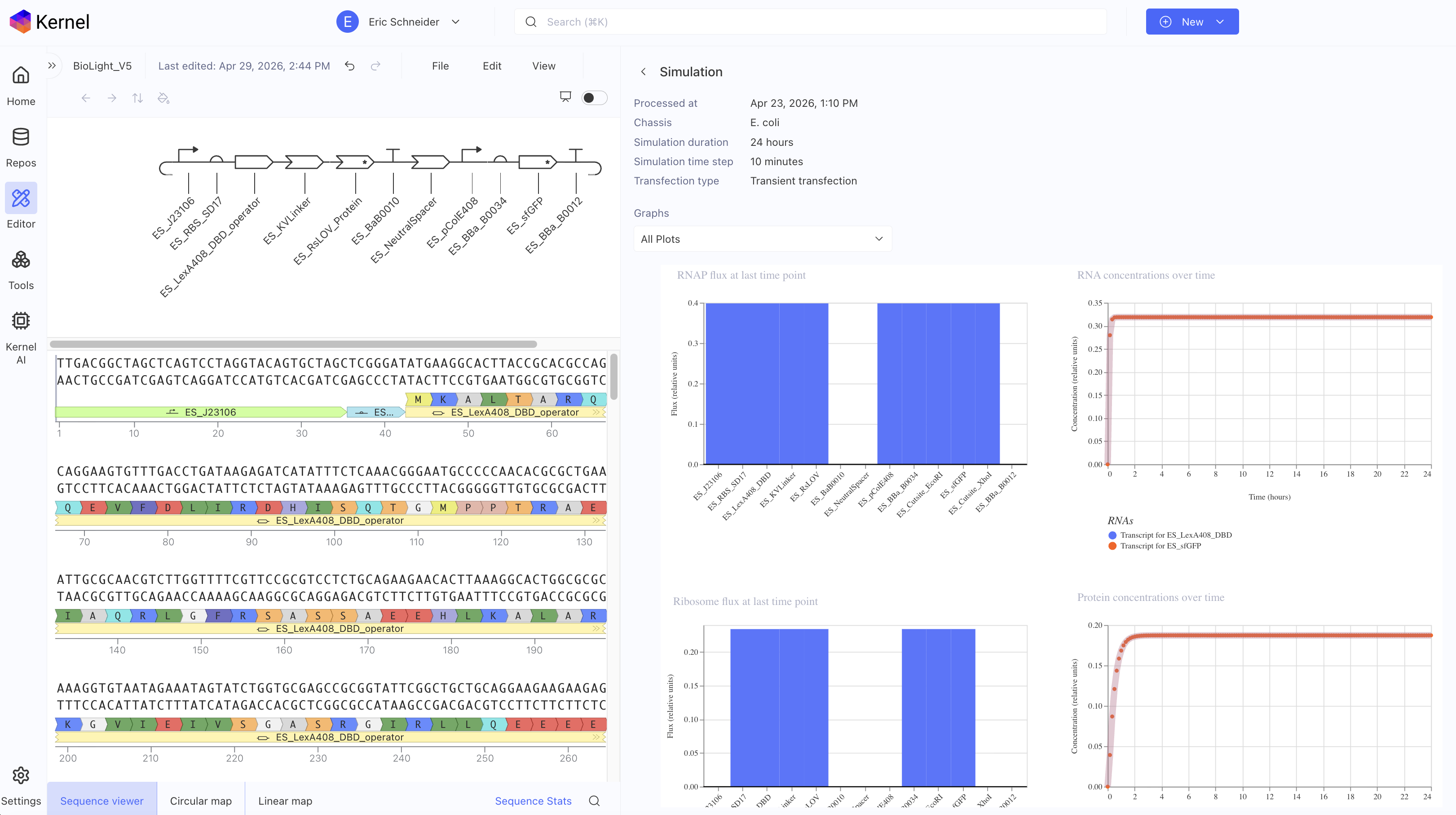 *Asimov Kernel Simulation: 24 hrs
Step 5 — AlphaFold structural prediction and key limitation
Following Benchling refinement, AlphaFold was used to predict the three-dimensional fold of the RsLOV–LexA408 fusion protein — using the codon-optimized, protein-derived sequence as the basis, ensuring structural prediction reflects the actual construct. AlphaFold produced a structurally confident model of the LexRO dimer, but with a critical and known limitation: it does not simulate FMN chromophore energy transfer or its photochemical interaction with the protein — meaning the predicted structure captures the overall fold with high confidence but cannot model the monomerization event triggered by 470 nm light. The result is a strong structural prediction paired with a weak link at the photochemical interface — the precise point where the dark-to-light state transition occurs.
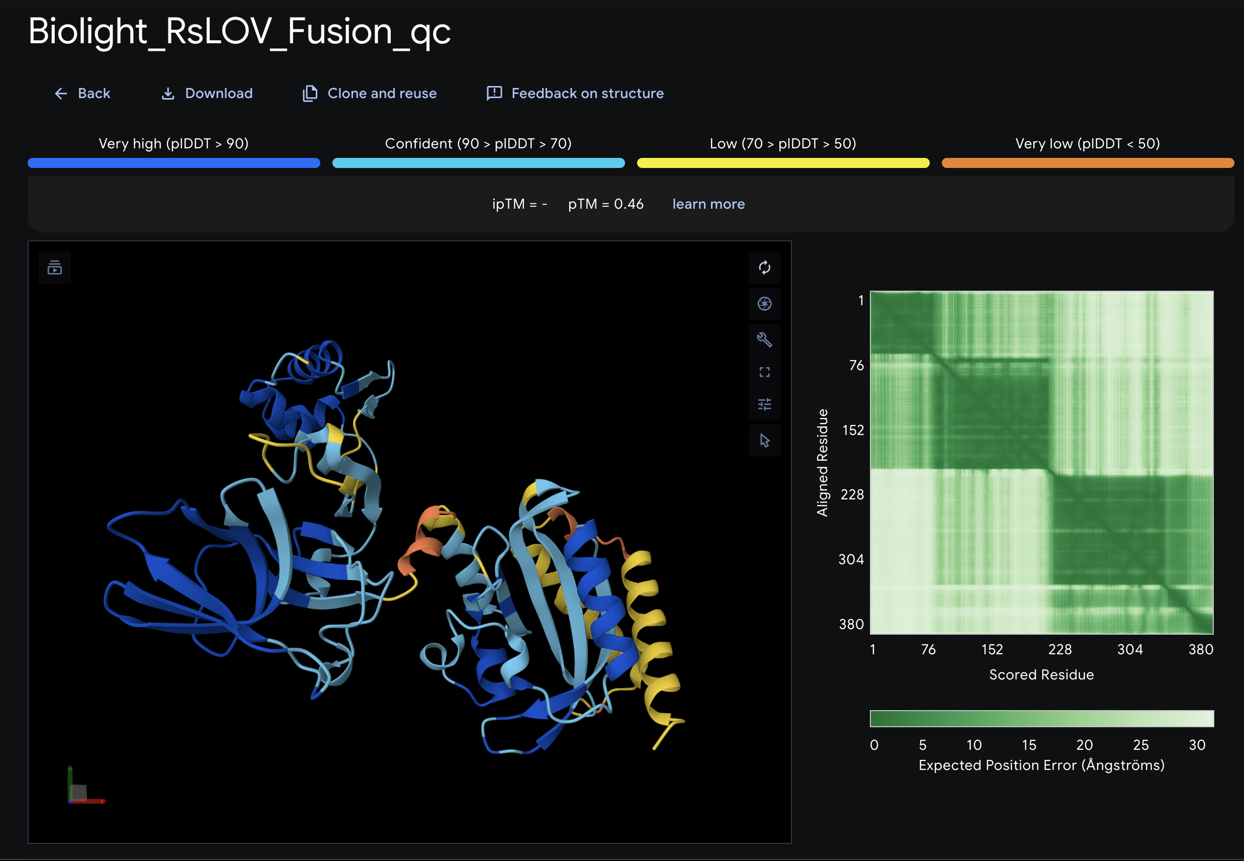 *AlphaFold Prediction : LexRO fusion of RsLOV-LexA408
Step 6 — ChimeraX MOA evaluation
ChimeraX resolved the AlphaFold gap through direct exploration of the dark-state crystal structure (PDB 4HJ4), enabling precise visualization of the FMN cofactor distance to the Cys55 terminus — the 4.324 Å gap that represents the photochemical trigger point for LexRO monomerization. The spatial relationship between the LexRO dimer and the pColE408 DNA binding/release interface was mapped, providing visual reinforcement that dark-state dimerization physically occludes the operator and represses sfGFP transcription, and supports the theory that the geometry of monomerization under 470 nm light is sufficient to uncover the promoter and permit expression.
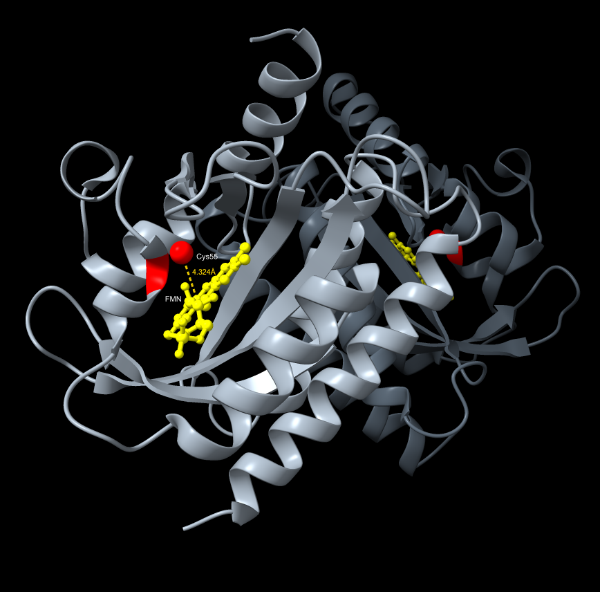 *ChimeraX Visualization FMN cofactor distance to the Cys55 terminus
The full six-step pipeline — candidate selection → IDT codon optimization → Benchling circular plasmid → Asimov Kernel parts and simulation → AlphaFold → ChimeraX MOA — forms a complementary design workflow where each tool’s features and limitations are explored, producing a construct that is sequence-verified, circuit-simulated, and structurally rationalized before a single wet-lab experiment begins.
Protocol Design 2 — Quality Control / Analysis: AS7341 Spectral Sensor as Photometric Calibration Instrument
Overview
The AS7341 11-channel spectral sensor serves a dual role in the Photoplasm system — first as a precision calibration instrument that characterizes the optical stack before any biological work begins, and second as a real-time plate reader during exposure and development. This protocol covers the calibration phase, which is a prerequisite for all Aim 2 — Test & Analyze (Development) exposure work. Full calibration specifications, Python scripts, and sensor deployment notes are documented in Photoplasm_Device_PreWork.md; the detailed build guide is published for future collaborators.
The optical stack and calibration geometry
The Photoplasm optical path is a darkroom enlarger rebuilt as a bio-imaging instrument: a 470 nm Cree XP-E2 LED ring delivers blue light through a condenser lens array that collimates and directs it into an even, parallel projection through the OLED digital image mask — where transparency is off and pixels are selectively on for masking — through a focusing lens, and onto the bacterial plate or agarose slab at approximately 10 inches from the nodal point of the focusing lens.
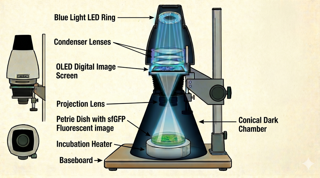 Photoplasm hardware stack: Image by NanoBanana 2
In initial testing this projection worked as designed, casting a sharp image onto the focal plane with measurable continuous tone gradations. The AS7341 is deployed at plate height to characterize this projection — reading the actual irradiance at the biological substrate plane rather than at the source, which is the only measurement that matters for exposure calibration.
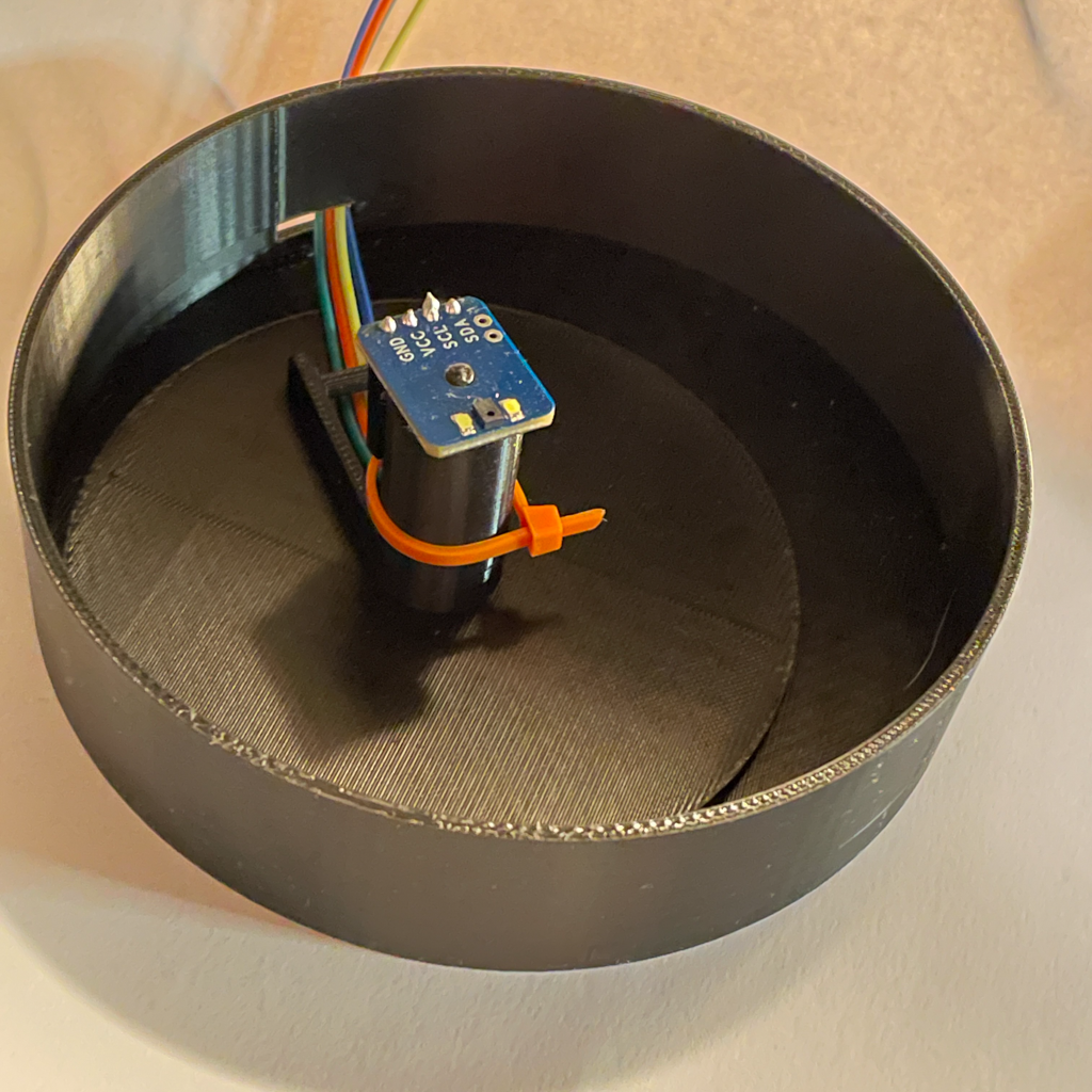 Wavelength Sensor(used for calibration)
Python calibration scripts and key findings
Three Python calibration scripts were written and run on the Raspberry Pi 5 to characterize the Photoplasm optical stack: photoplasm_cal01.py (retired from irradiance calibration after the key finding described below), photoplasm_cal02.py (three-state OLED irradiance measurement), and photoplasm_densitometer.py (16-step Bayer dither H&D curve sweep). A critical calibration principle emerged during early testing: the AS7341 is sensitive enough that even a change in projected pixel density — as introduced by a step-wedge mask — registers as an irradiance change at the sensor. This means any patterned mask in the optical path during calibration will cause the sensor to read spatial variation in the mask rather than the true uniform field irradiance.
The correct calibration approach is therefore full-frame uniform illumination with no mask pattern in the path — measuring the light field as the bacterial substrate will actually receive it. The step-wedge is preserved as a biological exposure tool for plate work, where spatial density variation is precisely what is being controlled, but it is not used during device irradiance calibration.
For the calibration sweep itself, a control-to-maximum irradiance run was executed — from direct unmodulated LED output through 100 PWM levels, downsampled to 16 standardized steps — producing a clean dose curve from minimum to maximum irradiance that defines the operating range of the Photoplasm device independently of any mask pattern. The densitometer script applied this approach using a 16-step Bayer ordered dither pattern across the full OLED pixel density range, and the AS7341 F2+F3 channel sum (445 nm + 480 nm, used as the 470 nm dose proxy since no single AS7341 channel falls at exactly 470 nm) showed a logarithmic response characteristic: steep toe at 0–25% pixel density, linear zone at 25–75%, and shoulder plateau at 75–100%, with a log fit of F2+F3 ≈ 138 + 22.5 × ln(density + 1) at R²=0.968.
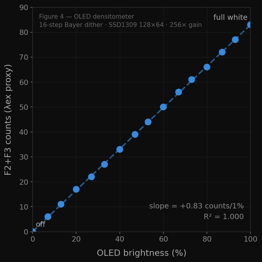
Densitometer Readings - (used for calibration)
This is the optical H&D curve of the Photoplasm device — confirming that the system produces a measurable, continuous-tone sensitometric response before a single bacterium has been exposed. An additional discovery emerged: the OLED digital image mask itself emits 470 nm light proportional to pixel density, making it an additive light source rather than a purely neutral mask — a finding that motivates the planned upgrade to an ILI9341 transmissive LCD.
Cree XP-E2 upgrade and f/8 aperture decision
Initial Aim 1 testing confirmed that the consumer-grade EBOOT LED ring measured approximately 2.0 µW/cm² at the substrate plane — approximately 50× below the eLightOn activation threshold of 100 µW/cm². The AS7341 calibration data provided the quantitative basis for the upgrade decision: Cree XP-E2 LEDs, with measured output 10–20× higher than the EBOOT array and a tighter wavelength specification centered at 470 nm, will comfortably exceed the activation threshold. The irradiance gate for Aim 2 — Test & Analyze (Development) is defined as ≥100 µW/cm² confirmed by the AS7341 at plate height before any biological exposure begins. The focusing lens will be set to f/8 — the optimal balance between image sharpness and depth of field for bacterial plate work. A lower f-stop risks out-of-focus regions across the agarose slab surface if the slab is not perfectly flat; a higher f-stop increases depth of field but reduces light reaching the substrate. f/8 is selected because agarose slabs and bacterial expression layers may vary slightly in surface topology — f/8 provides enough depth of field to accommodate this variation while maintaining adequate irradiance at the substrate plane with the Cree upgrade.
Timed duty cycle dosing and machine vision feedback
A key methodological innovation in the Aim 2 — Test & Analyze (Development) exposure protocol is the use of a timed duty cycle rather than a single continuous exposure. Bacterial cultures are allowed to grow in total darkness first, establishing baseline expression; a calibrated dose of 470 nm blue light is then delivered at the measured irradiance level, followed by a dark recovery period, then another dose — repeated across the exposure window to prevent over-expression and metabolic exhaustion of the host cells. The reversibility of the eLightOn / BioLightV5 mechanism makes this approach possible: because LexRO re-dimerizes in the dark and re-represses sfGFP transcription during recovery intervals, the system can be dosed, rested, and dosed again — allowing fine-tuning of the exposure across multiple cycles within a single 24-hour experimental run.
Code Sample (snippet) - PWM Duty Cycle for Raspberry Pi 5
Finding the optimal balance of dose duration, recovery time, and total cycle count is itself a deliverable of Aim 2, and the resulting duty cycle parameters will become part of the calibrated exposure protocol published in the open-source documentation. A Raspberry Pi Camera Module mounted in the Photoplasm dark chamber provides real-time machine vision feedback during the exposure cycle — capturing fluorescence pattern development at each dose interval and feeding image data into a self-correction algorithm that can adjust subsequent dose parameters based on observed expression response. This machine vision layer is the first implementation of an autonomous feedback loop in the Photoplasm system, and it represents the foundational data collection step for the Aim 3 — Learn & Refine (Visionary) large language model: as exposure data accumulates across multiple Photoplasm devices and experimental runs, the self-correction algorithm becomes a training dataset suitable for a shared neural network — a fleet-level learning model that improves calibration accuracy across all deployed devices over time.
Part D — Industry Council Companies
Identify any How To Grow (Almost) Anything Industry Council companies which are associated with your final project (optional).
Primary Partners
Ginkgo Bioworks (Aim 3 — Learn & Refine)
Ginkgo Bioworks is an essential partner for the Aim 3 — Learn & Refine (Visionary) cell-free protein synthesis path — the cloud lab infrastructure that transforms BioLightV5 from a live-culture wetlab construct into a stable, shippable, freeze-dried consumable manufacturable at industrial scale. Most significantly, Ginkgo Bioworks could serve as the provider of a cell-free protein synthesis system featuring a Photoplasm-compatible biosensor — a complete, ready-to-use biological kit that responds to 470 nm blue light and produces sfGFP output when exposed through the Photoplasm device. This would make Photoplasm a true distributed community kit: the Ginkgo-manufactured cell-free biosensor as the biological consumable, the open-source Photoplasm device as the exposure instrument, and the shared experiential activity data model as the learning layer.
This initiative recognizes the Eastman/Kodak photographic industry analogy made real, where the complexity lives in the consumable and the participant simply loads, exposes, and observes. Beyond the consumable model, if Photoplasm is validated as a third-party labware instrument compatible with Ginkgo’s automated cloud lab protocols, it could operate as an optogenetic exposure platform within the Ginkgo ecosystem itself — a named protocol element in a fully automated, remotely executed biological imaging workflow.
There may also be a living-cell pipeline reinforced by a fully automated biomanufacturing process which would extend the reach of the visionary aim to existing wetlabs undergoing cloud automation transformation.
Addgene (Aim 1 — Design & Build + Aim 3 — Learn & Refine)
pDawn-sfGFP plasmid #107741 — the validated control construct for Aim 2 — Test & Analyze (Development) — ordered and handled exclusively under Genspace BSL-1 protocols at the Genspace Node. Beyond immediate construct sourcing, direct engagement with Addgene during this project revealed a longer-term institutional pathway: becoming an MTA-ready lab (Material Transfer Agreement certified) is a formal Addgene requirement for any community lab that wishes to deposit or distribute plasmids through their repository. Pursuing MTA-ready status for the MakerSpace Charlotte BioArt Studio is an aspirational goal of Aim 3 — Learn & Refine (Visionary) — one that would formalize the studio’s capacity to receive, handle, and eventually contribute biological materials to the open plasmid commons, directly aligned with the two-step HTGAA Node authorization pathway described in Section 3.
Transfyr.ai (Aim 2 — Test & Analyze → Aim 3 — Learn & Refine)
Having attended the HTGAA guest speaker session, the connection between the Transfyr.ai observational learning model and the Photoplasm platform has become clearer and more specific. The Photoplasm device is a connected instrument — every exposure run generates structured experimental data (irradiance levels, duty cycle parameters, AS7341 spectral readings, machine vision outputs) alongside learner participation and engagement signals from the community lab context. This is precisely the observational data model Transfyr.ai is built to capture and analyze.
Photoplasm represents a novel category of an observational data source: a community-deployed scientific instrument that is simultaneously generating both experimental outcomes and participant engagement metrics in a single session. The Aim 3 — Learn & Refine (Visionary) goal of a fleet-level LLM becomes more achievable when paired with observational and experiential activitiy data from distributed device users over time.
I believe that a continued collaboration with Transfyr.ai may lead to novel use of activity-based tracking and measurement protocols known as IEEE 9274.1.1-2023 (xAPI 2.0) which I have deployed at global manufacturing scale, and can lead to measurable transformation of industry best-practices.
Supporting Partners
- New England Biolabs — DH5α competent cells, ampicillin, transformation reagents for Aim 2 wet-lab work at Genspace
- Asimov (Kernel) — circuit-level logic design of BioLightV5, used in Aim 1 — Design & Build
- Twist Biosciences — essential synthesis pipeline partner for BioLightV5 clonal gene order
Part E — Workflow Figures
Figure 4.1 — Aim 2 Protocol: Two Blue Light Tests. Visual illustration of the sequential blue light testing protocol within Aim 2 — Test & Analyze (Development). Left panel: Blue Light Test 1 — MVFV — two test tubes post-transformation, one illuminated at 470 nm, one dark, with AS7341 readout and go/no-go gate. Right panel: Blue Light Test 2 — Photoplasm step-wedge calibration — device with OLED digital image mask projecting a 16-step Bayer dither onto an agarose slab, AS7341 capturing dose-response, and the resulting bacterial H&D curve. (FormLabs illustration — attach on submission.)
Figure 4.2 — Asimov Kernel simulation graph. Predicted sfGFP expression output from BioLightV5 circuit simulation. Spike in expression confirmed; dark-state repression not captured due to mammalian model limitation and absence of FMN chromophore photochemistry modeling. (Screenshot from Asimov Kernel — attach on submission.)
Figure 4.3 — BioLightV5 non-linear design network. SVG diagram showing the iterative, non-linear pipeline from candidate selection through eLightOn reconstruction, Benchling, IDT codon optimization, Asimov Kernel, AlphaFold, and ChimeraX, with dashed feedback loops at two key iteration points. (Inline SVG — exported from interactive widget, converted offline.)
Appendix — Standalone Protocol Documents
| Document | Version | Scope |
|---|---|---|
Photoplasm_BioLightV5_Protocol.md | v0.3.0 | Primary wet-lab protocol, phases P0–P6 |
Photoplasm_Device_PreWork.md | v0.1.0 | Device prep, Cree LED irradiance gate, fallback rig |
Aim2_Protocol_AgaroseSlab.md | v0.2.1 | Agarose slab embedding method (adapted from Tabor 2011) |
pDawn_Backup_Protocol.md | v0.1.0 | Fallback protocol if BioLightV5 sequence fails |