Neuromorphic Circuits
Intracellular Analog Neural Networks
1. Advantages of IANNs over traditional circuits
According to Ron Weiss lecture, Intracellular Analog Neural Networks (IANNS) offer several advantages as compared with classical Boolean genetic circuits (combination of simple on/off switches):
Continuous signal: IANNs allow the integration of continuous signals: this processing is much closer to what happens in cell biology. For instance, a Boolean circuit can assess whether the protein CasE is present or not, while the IANNs can compute the concentration of CasE in the cell.
Non-linear computing: IANNs allow weighted summations and substractions through universal digital logic (AND + NOT gates). In other words, the computation allows some inputs to have more importance than others. This processing mimics the complexity of analog neural networks and by extension, also intracellular processes in a way which is closer than a circuit only made of on/off gates.
Programmability: Nodes can be composed into multi-layer networks (e.g. bandpass circuits). This feature allows IANNs to compute complex tasks with high efficiency, and for tuning the circuits without having to rethink everything.
2. Example of a useful application for an IANN
The example of cancer cell classification given by Ron Weiss during his lecture is interesting for my final project: the same approach can be implemented to “assess the microbiotic landscape(s) of perimenopause”*. Biological states such as cancer or hormonal transitions don’t involve one but multiple parameters. IANNs can be used to track these changes with more precision and at a much earlier time point than a common single biomarker screening.
In Multi-input RNAi-based logic circuit for identification of specific cancer cells Weiss and al. use IANNs to determine whether a cell is cancerous or not. The authors use the levels of different types of microRNAs known to be involved in cancer as inputs (X1: biomarker 01, X2: biomarker 02, X3: biomarker 03). After integration of these inputs through the hidden layers of the circuit, a specific response is triggered depending on the classification of the cell. For instance, the “cancer cell” signature could correspond to intracellular biomarkers X1 being high, X2 high and X3 low. If the output equals 1 (or “true”) for “cancer cell”, the circuit triggers apoptosis (cell death) in these cells. If the miRNAs levels do not fit the cancer signature, nothing happens.
Possible design limitations:
- Variable efficiency due to different “cancer signatures” depending on the patients or patient groups (e.g. age, sex, type of cancer, co-morbidity etc.). However, this limitation could possibly be overcome by use of AI with a personalized medicine approach.
- While this method sounds more promising than the current anti-cancer treatments (e.g. chemotherapy), the final output remains binary. This means that the challenge of defining thresholds may still remain: too low and the signal to noise ratio (SNR) might lead to errors, too high and healthy cells get killed.
- Side effects: for instance in the short-term, unwanted apoptosis in healthy cells if the signature is not specific enough and in the long-term, unwanted adaptive decreased vigilance of the immune system towards cancer cells. Unexpected side effects due to the “black box” problem: interpretation, bias and trust in the deep layers of the model.
3. Perceptron diagrams
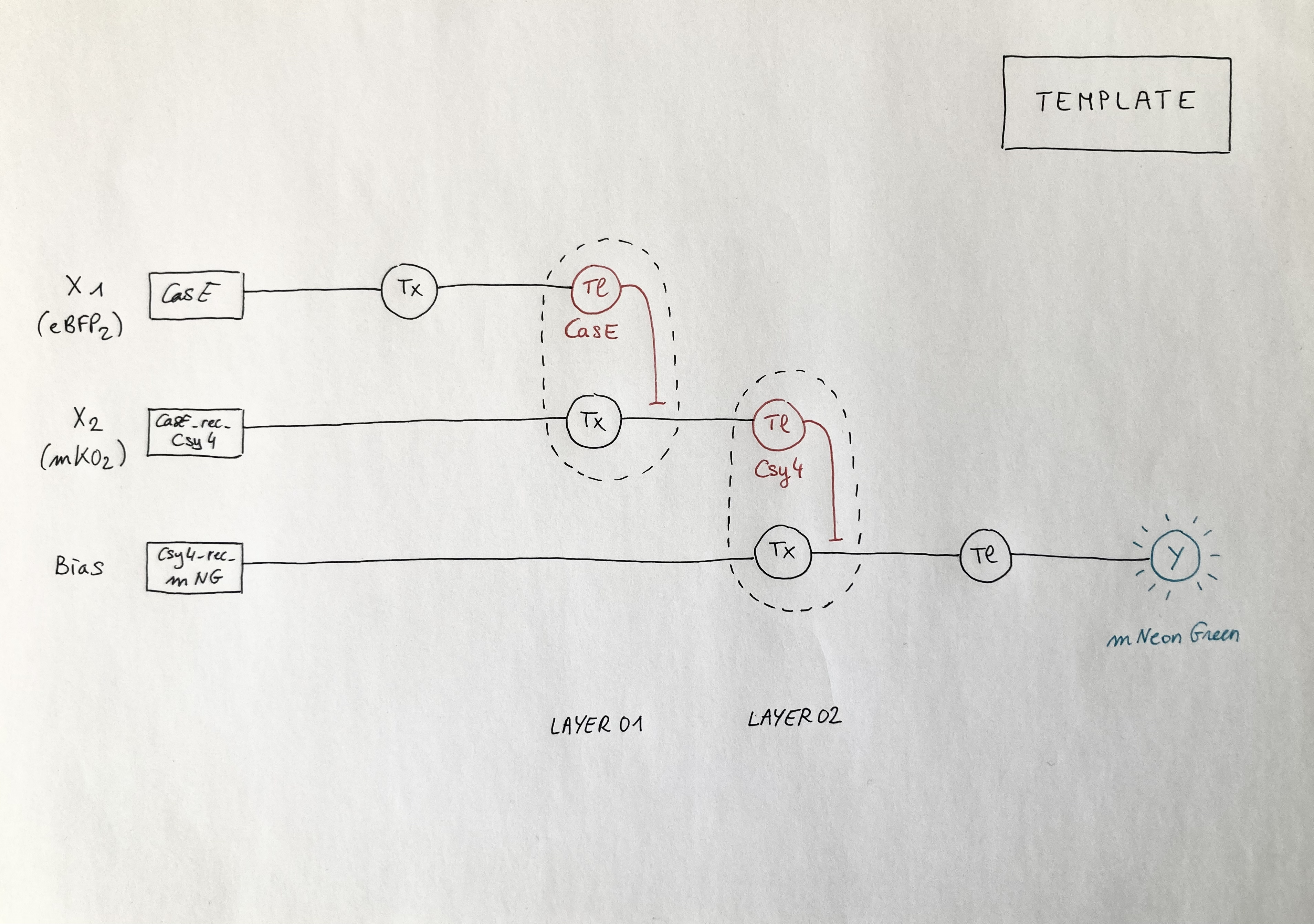
Genetic Circuit Design Template
Below is the diagram of the perceptron corresponding to the template given for the Neuromorphic Wizard software: it depicts a two-layers perceptron where the X1 input is DNA encoding for the CasE endoribonuclease (layer 1), the X2 input is DNA encoding for the Csy4 endoribonuclease (layer 2) and the bias output is the expression of the fluorescent protein mNeonGreen (mNG). Marker X1: eBFP2 ; Marker X2: mKO2 ; ERN01_rec_ERN02: endoribonuclease 01 regulates endoribonuclease 02; Y: output; Tx: transcription; Tl: translation.
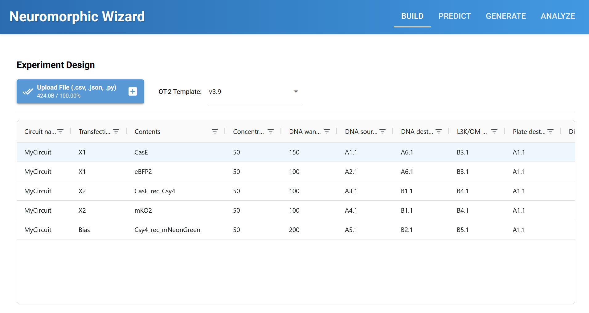
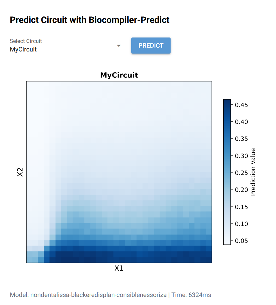
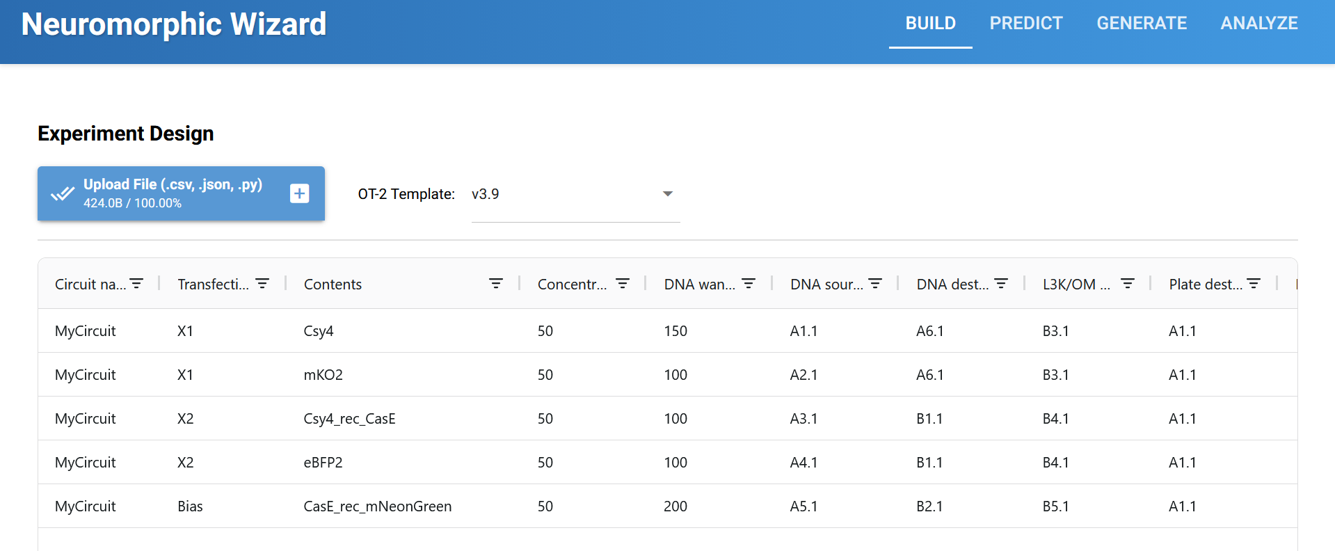
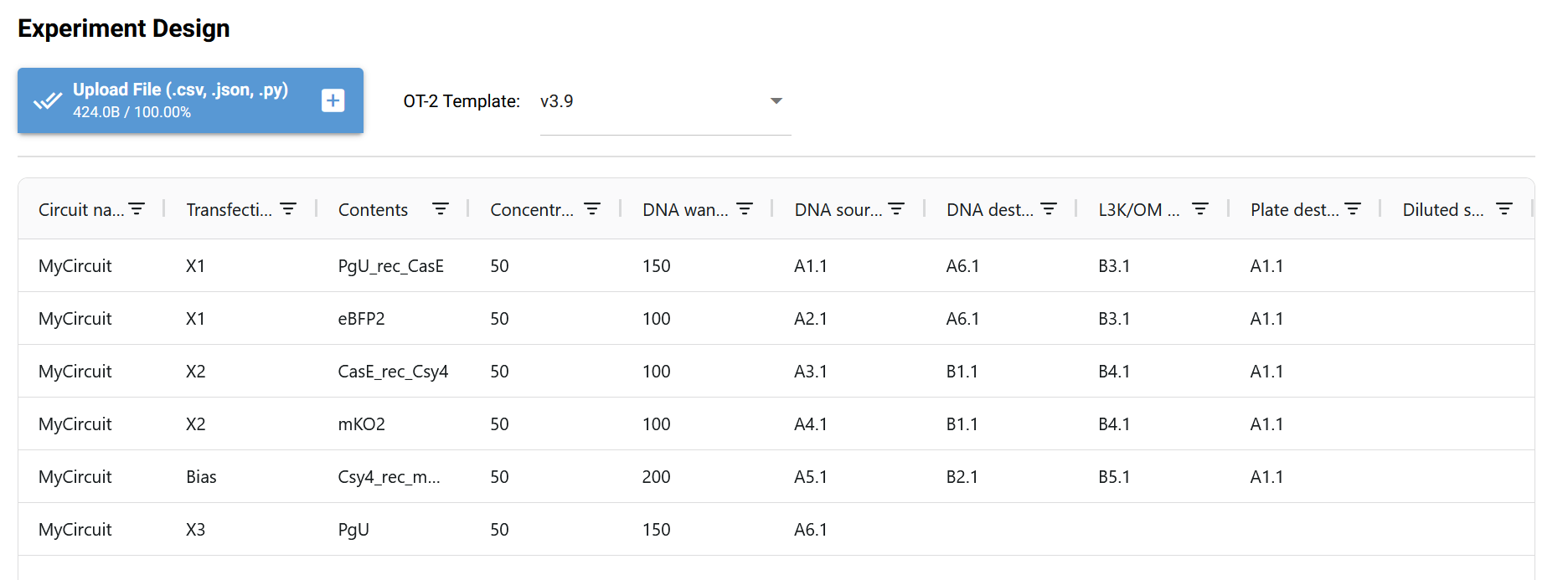
Neuromorphic Wizard Template Build and Prediction:
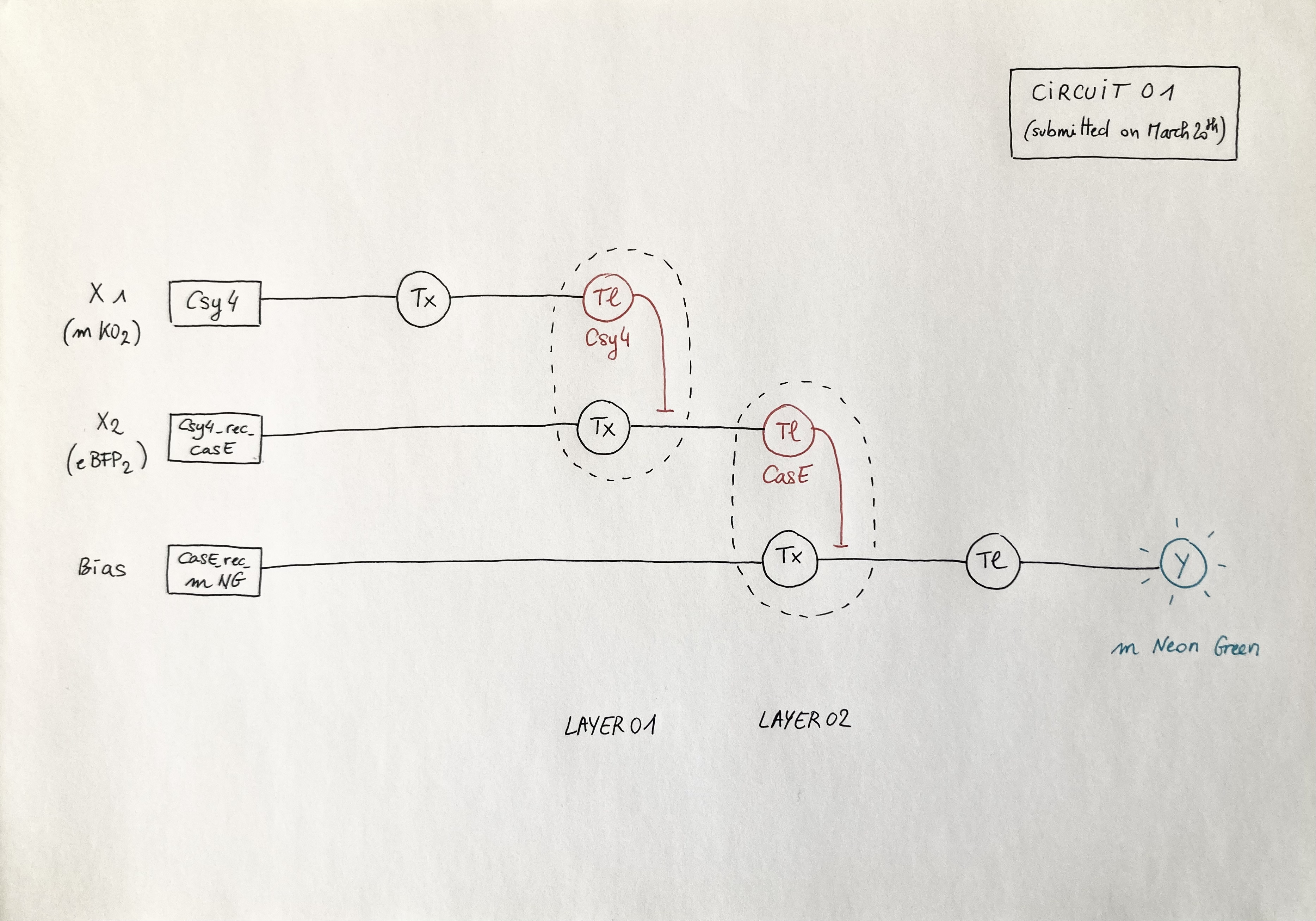
Circuit 01 (submitted on March 20th)
Below is the diagram of the perceptron I submitted on Friday 20th. It depicts a circuit similar to the template but with a swap between X1 and X2: the X1 input is DNA encoding for the Csy4 endoribonuclease (layer 1) and the X2 input is DNA encoding for the CasE endoribonuclease (layer 2). Marker X1: mKO2 ; Marker X2: eBFP2 ; ERN01_rec_ERN02: endoribonuclease 01 regulates endoribonuclease 02; Y: output; Tx: transcription; Tl: translation.
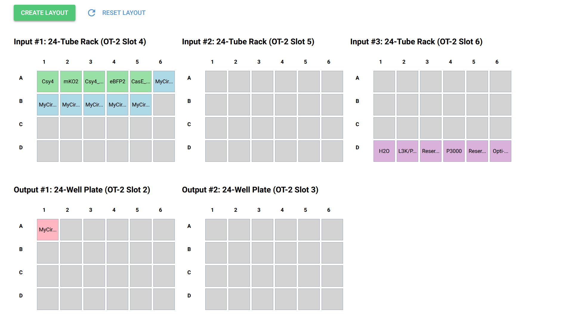
Circuit 01 Build, Layout and Prediction:
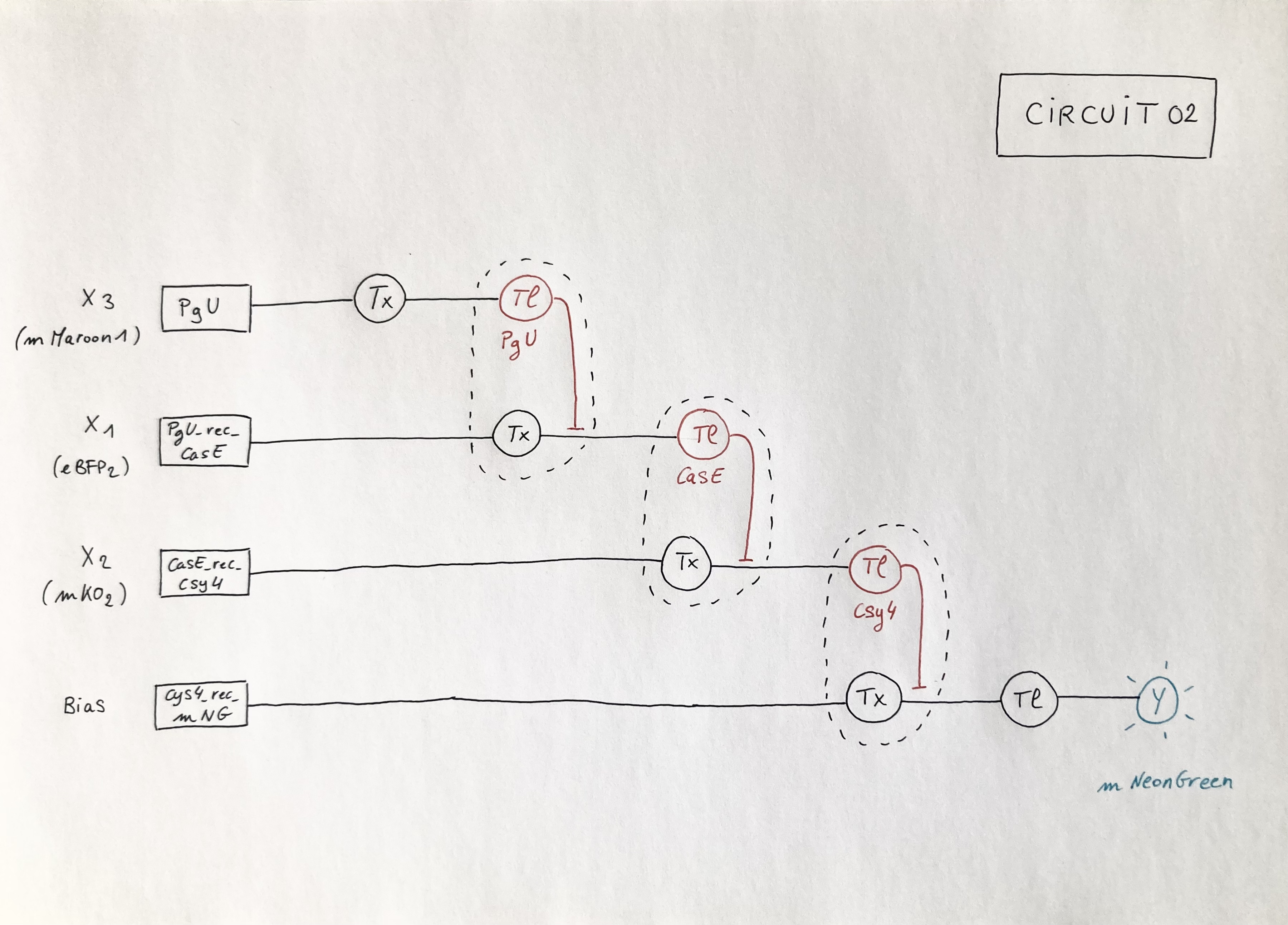
Circuit 02 : three-layers perceptron
Below is the diagram that depicts a circuit similar to the template but with one added layer in which X3 inputs an endoribonuclease (PgU) that regulates X2 output (Case). Marker X1: mKO2 ; Marker X2: eBFP2; Marker X3: mMaroon1 ; ERN01_rec_ERN02: endoribonuclease 01 regulates endoribonuclease 02; Y: output; Tx: transcription; Tl: translation.
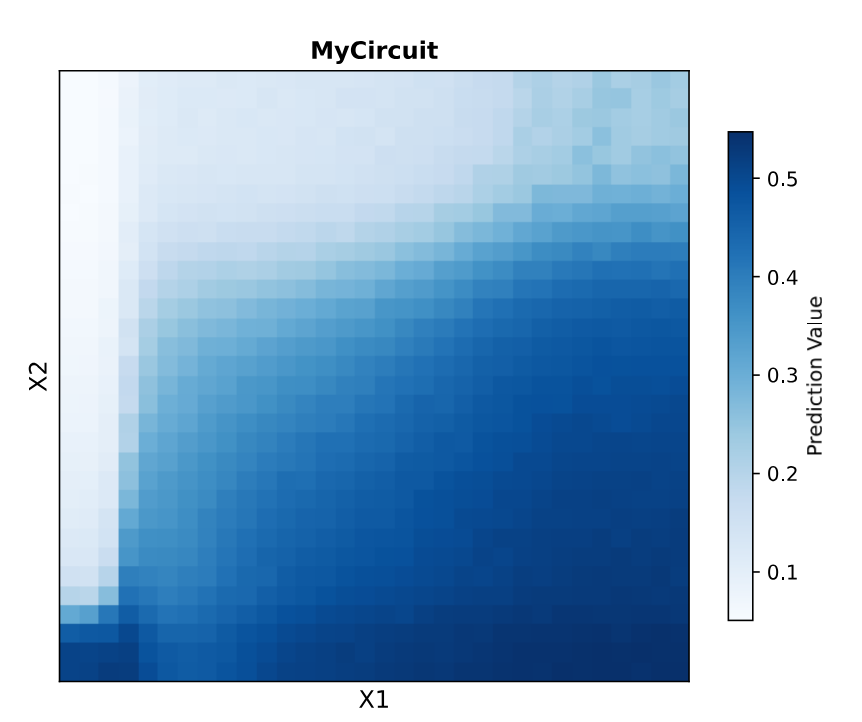
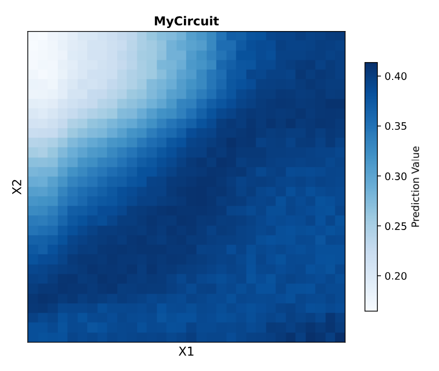
Circuit 02 Build and Prediction:
Documentation
Software Installation
The installation of the software was an assignment in itself and included watching again the BioClub recitation and a change of device. Reopening the software worked smoothly though. Note for later use:
- Look for the Anaconda PowerShell app in the search menu and open it as administrator
- In the command window, type:
- cd C:\NeuromorphicWizard
- conda activate neuro_wiz
- python main.py
- Don’t click anywhere until the software opens in a new tab (internet browser, it can take some time)
Process
At first, because a proper explanation of the building blocks was missing, it was difficult to understand the correspondance between the design of the perceptron and the Neuromorphic Wizard build. I worked directly on the software and exchanged a few blocks following an intuitive logic until I obtained a prediction instead of an error message. This led me to create and submit Circuit 01 on March 20th but I was missing the corresponding perceptron.
In a second step, after rewatching very carefully Ron Weiss’s lecture and the MIT recitation, I finally managed to gather enough elements to understand the building blocks and draw the diagrams corresponding to the builds of the template and Circuit 01. From there, I draw Circuit 02 and obtained the corresponding prediction in the Neuromorphic Wizard software. Total DNA concentration above 650 mg did not trigger an error message but changing the levels to stay under that threshold did.
Afterwards, I tried to incorporate a negative feedback loop into Circuit 01 : csy4_rec_Case but got a error message. Same when trying to translate my final project idea into a diagram.
Next steps:
- Ask for explanation / more information to understand DNA wanted and other columns in the NeuroWizard Build.
- Troubleshoot the error messages to obtain predictions for Circuit 03 and Circuit 04.