Week 6 HW: Genetic Circuits Part I
Contents
DNA Assembly questions
- What are some components in the Phusion High-Fidelity PCR Master Mix and what is their purpose?
- Phusion DNA polymerase - a high fidelity DNA polymerase, which means that it is an enzyme that adds single nucleotides to extend a DNA chain along a template with some sort of proof-reading ability. It is used for PCR, which means it has to be thermostable.
- dNTPs - single nucleotide bases to be used by the polymerase to make DNA
- buffer - buffer is used primarily for controlling the pH of the PCR reaction, but it also includes MgCl2 which is a required co-factor for the DNA polymerase.
- What are some factors that determine primer annealing temperature during PCR?
Primer annealing temperature is affected by the length of the primer and the GC content primarily. - There are two methods from this class that create linear fragments of DNA: PCR, and restriction enzyme digests. Compare and contrast these two methods, both in terms of protocol as well as when one may be preferable to use over the other.
PCR is a method to produce many copies of a DNA sequence for which you already have a template. It requires a thermocycler, and PCR mix (thermostable DNA polymerase, dNTPs, appropriate buffer). To use it, you need to have template DNA and primers designed to bookend the sequence of interest. Restriction digests can linearize circular DNA or trim DNA sequences. It requires a heat block or incubator, the relevant restriction enzymes, and appropriate buffer. To use it, you need to have (typically a medium or high concentration amount) DNA that contains your sequence of interest already bookended by restriciton enzyme cutsites. Restriction digests can produce sticky ends or blunt ends; PCR will always produce blunt ends. Both methods will typically require some sort of purification step before further use (DNA cleaning and concentrating; gel extraction). PCR is useful when you need more of a particular sequence of DNA, when you want to make point mutations within a sequence (multi-step process), to add short sequences to the ends of the DNA sequence (such as restriction enzyme cutsites, adaptors, or overlaps). Restriction digestion is useful when you need to remove an insert from a plasmid backbone, to linearize a vector for electrophoresis or other analysis, and for restriction-digest cloning (including ensuring insert and vector have appropriate sticky ends for directional insertion). - How can you ensure that the DNA sequences that you have digested and PCR-ed will be appropriate for Gibson cloning?
Ideally you would design and test in silico to ensure overlaps are appropriate. My first couple times trying Gibson assembly, i wrote it out by hand to convince myself i had done it correctly, but many molecular biology software options can now assist with this as well. You can exactly confirm your purified DNA fragments prior to Gibson assembly by sequencing them, but you can also just get a good idea of their size (which would at least tell you if you PCR’d a very different or non-specific products) by running them on a gel. - How does the plasmid DNA enter the E. coli cells during transformation?
During a heat shock transformation, you shock the E. coli cells with an abrupt temperature change from on ice at 0°C (or sometimes room temperature around 20°C) to 42°C. This opens pores within the cell membrane that allow DNA to enter the cells, due to prior treatment with CaCl2 to neutralize the negative charge of the DNA. - Describe another assembly method in detail (such as Golden Gate Assembly).
- Explain the other method in 5 - 7 sentences plus diagrams (either handmade or online).
Golden Gate Assembly can be conceptualized as a cross between restriction digest cloning and Gibson Assembly. Like restriction digest cloning, restriction enzymes are used to digest both the insert and the vector to create compatible sticky ends for directional insertion. However, it uses Type IIS restriction enzymes (such as AarI) that cut outside their recognition site. Therefore with correct design, the recognition sites are removed in assembly. This allows for plasmid construction similar to Gibson assembly: design your insertion fragments and vector backbone to have compatible overhangs/overlaps with the adjacent sequences (often added during primer design in PCR), then add all fragments to the reaction mix which includes both a nuclease and a ligase for assembly. In Golden Gate assembly, the Type IIS restriction enzyme(s) find their recognition sites, cut nearby (at a pre-identified base), resulting in the designed 4-base overhangs. These overhangs can connect with matching overhangs from either the original construct or the intended adjacent fragment, which will be ligated into a closed dsDNA molecule (if the original construct is re-ligated, then the Type IIS enzyme again finds the recognition site and cuts again, thereby improving the efficiency).
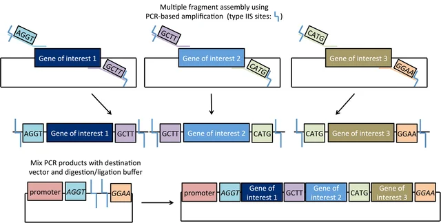 Figure from Addgene’s Golden Gate Cloning page.
 - Model this assembly method with Benchling or Asimov Kernel!
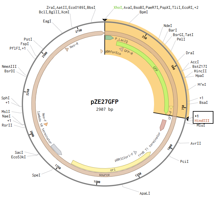
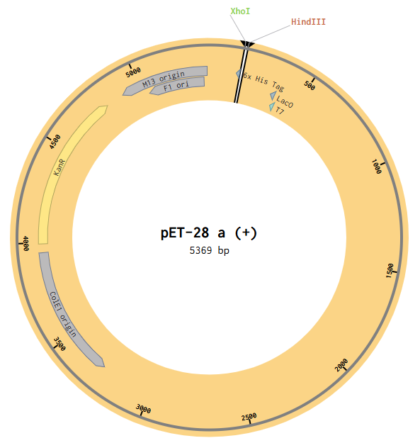
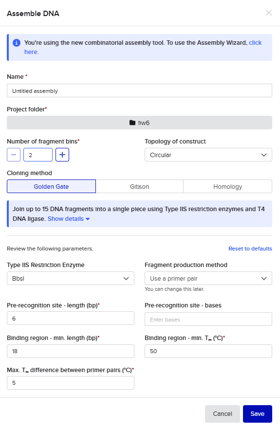
To compare assembly methods, I used Benchling’s Assembly Wizard tool to simulate the same plasmid construction using restriction digest, Gibson assembly, and Golden Gate assembly. My target plasmid is called “pGFP”, with a pET28a(+) backbone and an insert containing the gene for green fluorescent protein (GFP) under constitutive promoter P_LacIQ from plasmid pZE27GFP. I started by importing both pET28a(+) and pZE27GFP into Benchling from Addgene. I used Benchling’s auto-annotation tool on pET28a(+) for annotations. pZE27GFP was already annotated, but was missing the annotation for P_LacIQ, so I added an annotation from that by downloading the Genbank file from the Addgene site and using CTRL-F on the sequence to identify it in the original file. I wanted these annotations so that I knew the locations of the relevant sequences in my files for easier visual identification during the cloning simulation. Note that the GFP translation in the pZE27GFP file didn’t include the stop codon, but the stop codon was present, just not included in that translation annotation, and I was too lazy to fix this, so I just remembered that my sequence of interest included the three bases past the end of the translation annotation.
- Explain the other method in 5 - 7 sentences plus diagrams (either handmade or online).
Golden Gate Assembly can be conceptualized as a cross between restriction digest cloning and Gibson Assembly. Like restriction digest cloning, restriction enzymes are used to digest both the insert and the vector to create compatible sticky ends for directional insertion. However, it uses Type IIS restriction enzymes (such as AarI) that cut outside their recognition site. Therefore with correct design, the recognition sites are removed in assembly. This allows for plasmid construction similar to Gibson assembly: design your insertion fragments and vector backbone to have compatible overhangs/overlaps with the adjacent sequences (often added during primer design in PCR), then add all fragments to the reaction mix which includes both a nuclease and a ligase for assembly. In Golden Gate assembly, the Type IIS restriction enzyme(s) find their recognition sites, cut nearby (at a pre-identified base), resulting in the designed 4-base overhangs. These overhangs can connect with matching overhangs from either the original construct or the intended adjacent fragment, which will be ligated into a closed dsDNA molecule (if the original construct is re-ligated, then the Type IIS enzyme again finds the recognition site and cuts again, thereby improving the efficiency).
Restriction Digest
Opening the pZE27GFP file to the plasmid map view, I selected the Digests tool to show all single cutters on the map, and identified ones that were near the ends of goal insertion sequence (outside P_LacIQ and GFP): XhoI and HindIII.
Then I opened the pET28a(+) file to the plasmid map view, and selected the Digest option to only show the selected enzymes, and found these two enzymes cut in the insertion locus on the plasmid (between the T7 promoter and the His-tag).
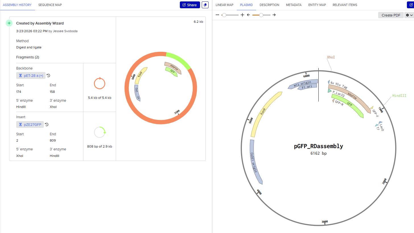
Since both enzymes were present on both starting constructs, I used the Assembly Wizard tool for Restriction Digest cloning, and selected the backbone and insert by highlighting the above sequences with the selected enzymes.
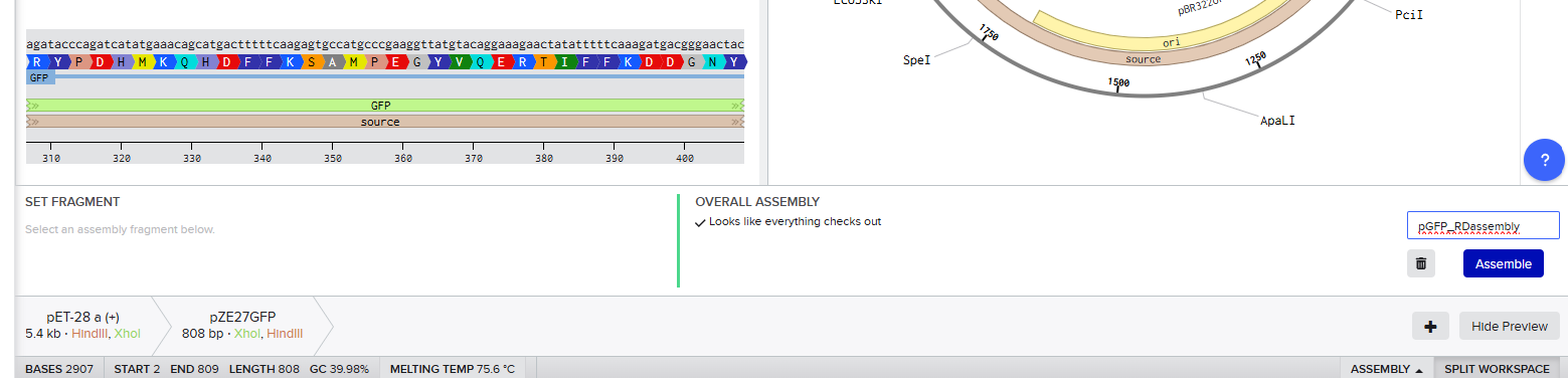
This resulted in a final assembly of pGFP_RDassembly. Note that both the XhoI and HindIII recognition sites are preserved in the final construct. While sticky-ended enzymes allow for directional insertion, this insert does not require directional insertion because it contains both the promoter and the gene. This is important because technically the insert is backwards for the vector as intended (for the T7 promoter and His-Tag on the backbone).
Gibson Assembly
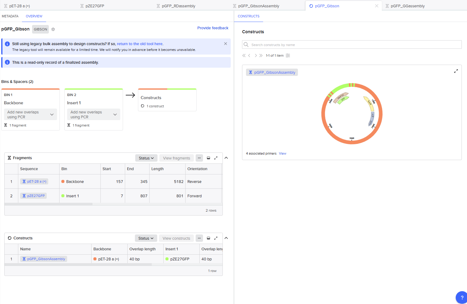
For the Gibson assembly method, I started by opening the Assembly Wizard, and selecting the Gibson option, and opting to try the new combinatorial assembly tool instead. I retained all the default options.
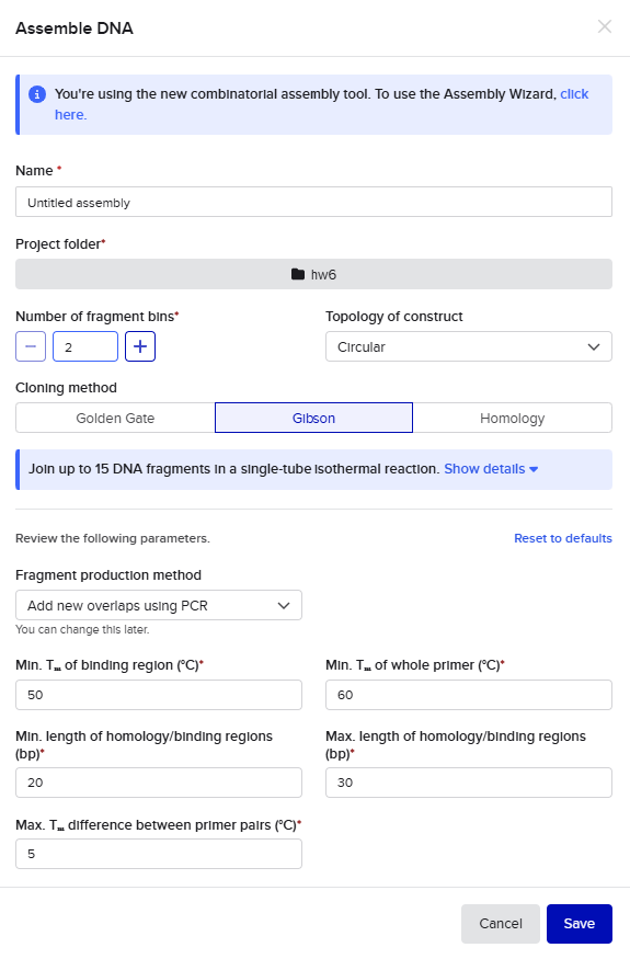
This resulted in a final assembly of pGFP_GibsonAssembly. The primers were auto-generated by the tool, and are visible in the Benchling files for pET28a(+) and pZE27GFP the the naming convention following “pET28a-GA_forward”. The PCR products used in the final assembly are here (insert) and here (backbone).
Golden Gate Assembly
For the Golden Gate assembly method, I similarly started by opening the Assembly Wizard, used the new combinatorial assembly tool for Golden Gate. I retained all the default options. I selected “Use a primer pair” as the option under “Fragment production method”, and then retained the default options that auto-populated. Upon selecting my insert and backbone sequences, the tool threw a warning for a recognition site for the Type IIS enzyme within one of those sequences, so I went into the tool settings to instead select AarI as my enzyme. AarI was chosen somewhat arbitrarily because I’ve used it before; if it had also thrown an error, I would have simply gone down the list until I found a compatible enzyme that wouldn’t cut inside my sequences.
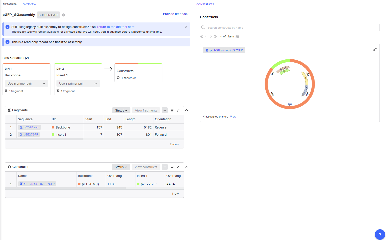
This resulted in a final assembly of GFP_GGassembly. The primers were auto-generated by the tool, and are visible in the Benchling files for pET28a(+) and pZE27GFP the the naming convention following “pET28a-GG_forward”. The PCR products used in the final assembly are here (insert) and here (backbone). Note that both fragments contain AarI recognition sites, but the final construct does not.
Asimov Kernel
See repository JKS_hw6 in Asimov Kernel.
Repressilator:
Repressilator reconstruction:
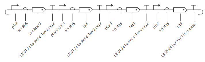
My initial attempt looks like
The Terminator chosen (L3S2P24 Bacterial Terminator) is the only one available in the Characterized Bacterial Parts repo. The H1 terminator was chosen arbitrarily as the shortest RBS; I just wanted the same RBS for each promoter-gene combo. I wanted to add a backbone, but there’s no backbone available in the Characterized Bacterial Parts repo. Because the homework instructions said to use only the parts in this repo, I figured I’d try this first without the backbone.
Unfortunately, this didn’t work. The outcome of my first simulation (E coli, 24h, 30min, no ligands) is below. Notice the lack of oscillations in the transcript and protein concentrations over time.
I have two potential solutions for this that I can think of before I check the pre-made Repressilator: first, I don’t have a backbone, which I do think I need, but I did still get a simulation without it, so maybe I don’t. Second, I don’t have a reporter protein. My recollection of the Repressilator paper includes a fluorescent output, so I’ll try adding a reporter gene next.
Second attempt:
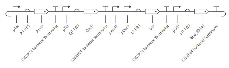
pTet was chosen arbitrarily - it could have been any of the three promoters used prior. H1 RBS was used again for consistency. LitR was chosen arbitrarily as a reporter gene because I couldn’t find a fluorescent protein within the Characterized Bacterial Parts repo.
Unfortunately, this gave more or less the same kind of output with no oscillations. I’ll try adding in a backbone from outside the Characterized Bacterial Parts repo, but if that doesn’t work then I’ll have to go back and reference the demonstration repressilator. Adding pUC-SpecR-v1 backbone, but it didn’t change the output.
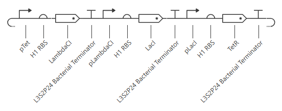
Checking the repressilator in the Bacterial Demos repo, I’m honestly not totally sure why mine didn’t work. It looks really similar:
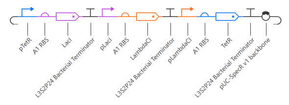
The terminator and backbone used are the same ones as I used. It has LacI/LambdaCI swapped from my original construct, but it should still work. Oh! I see - I accidentally grabbed pTet not pTetR originally. I went back and removed my pTet-LitR section, to return to my original construct, and then I replaced the pTet with pTetR.
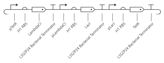
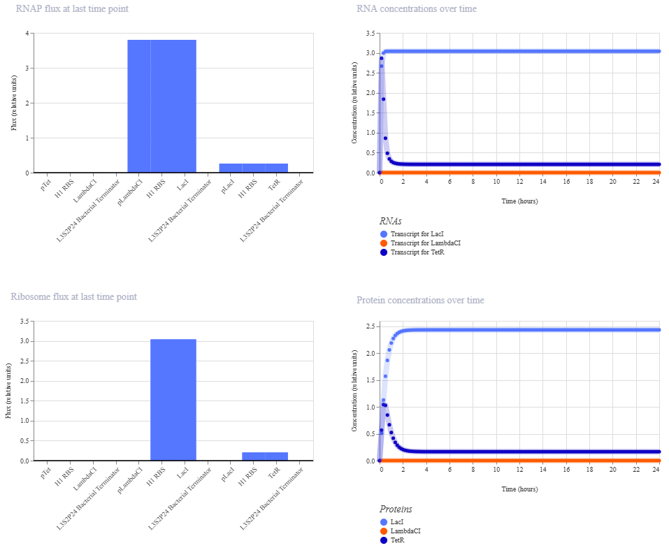
This worked! Here’s my new output:
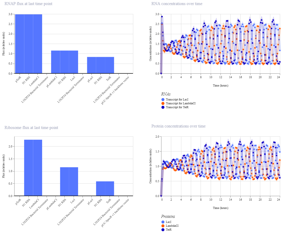 And here’s the oscillations that I wanted to see. Awesome!
Construct1: OR gate
Construct 1: OR gate
Initial construct
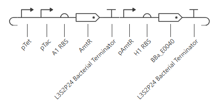
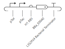 pTet is activated by aTc, pTac is activated by IPTG. BBa_E0040 is from the iGEM registry; encodes for GFP.
If aTc or IPTG is present, then GFP will be expressed.
pTet is activated by aTc, pTac is activated by IPTG. BBa_E0040 is from the iGEM registry; encodes for GFP.
If aTc or IPTG is present, then GFP will be expressed.
Expected output:
| aTc | IPTG | Output |
|---|---|---|
| 0 | 0 | 0 |
| 1 | 0 | 1 |
| 0 | 1 | 1 |
| 1 | 1 | 1 |
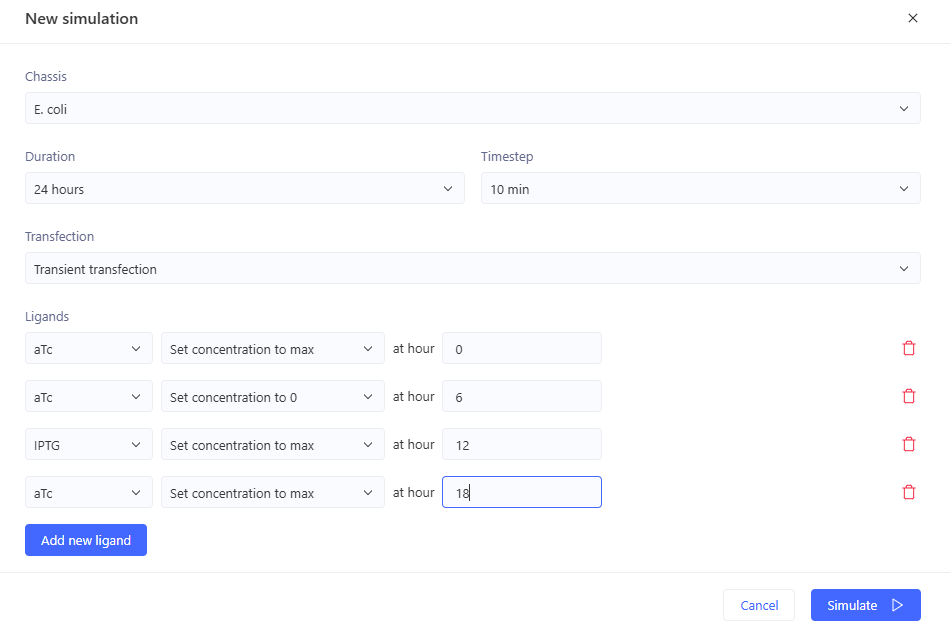
Simulation:
0-6hr: no ligands => no output
6-12 hr: aTc => GFP expression
12-18hr: IPTG => GFP expression
18-24hr: aTc+IPTG => GFP expression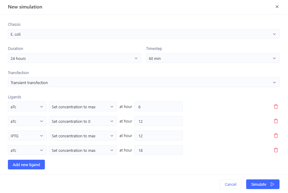
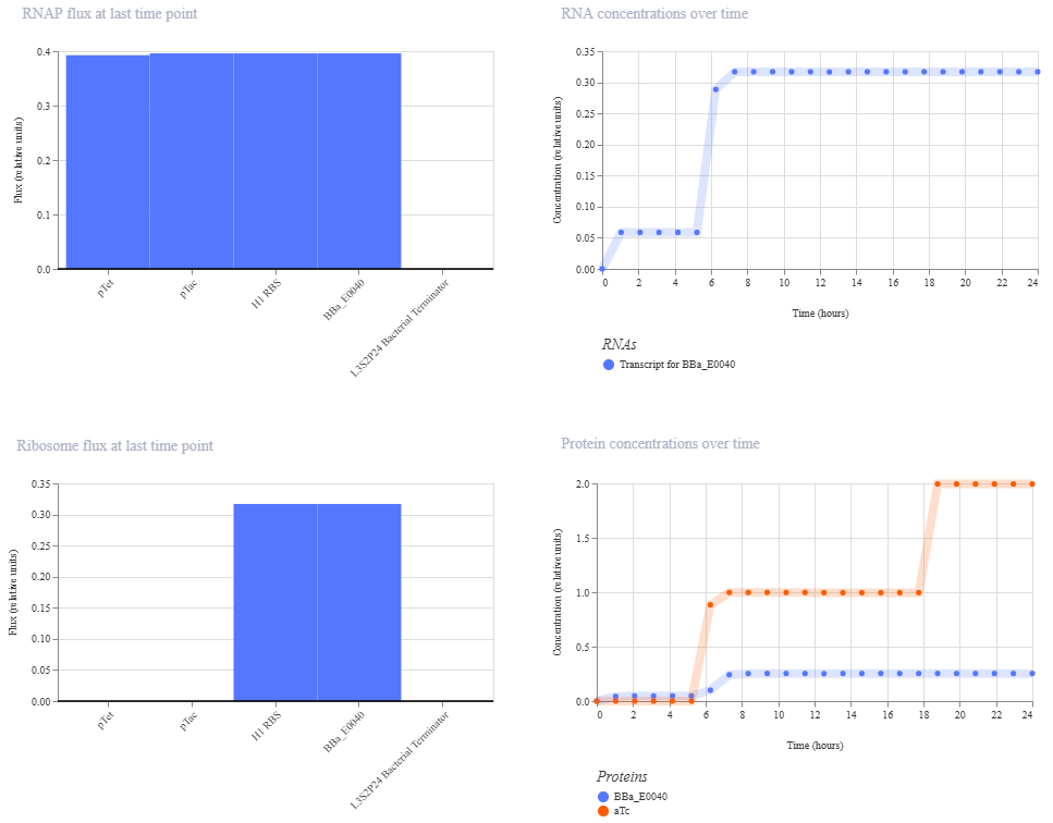
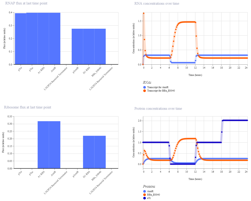
I’m a little surprised that there was as much of a difference between aTc and IPTG alone, but considering we are just looking at expression or not (rather than how much expression), i think this still worked. I am curious if I flip the order of pTet and pTac if that changes it at all. Kept the ligand amounts and times the same.
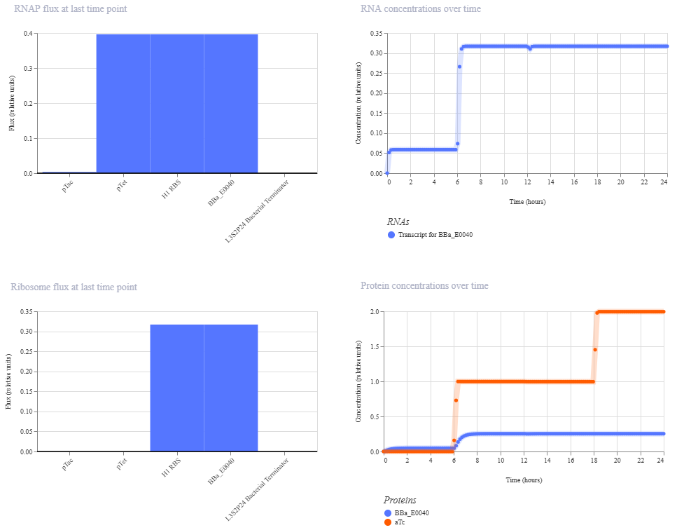
Just about the same. This makes me think that maybe setting the aTc concentration to 0 at time 12hr is maybe not working well, or maybe pTac is just that much stronger of a promoter than pTet.
Construct2: NOR gate
Construct2: NOR gate
Initial construction:
pTet is induced by aTc, pTac is induced by IPTG. BBa_E0040 encodes GFP. If neither aTc nor IPTG are present, then GFP will be expressed.
Expected output:
| aTc | IPTG | Output |
|---|---|---|
| 0 | 0 | 1 |
| 1 | 0 | 0 |
| 0 | 1 | 0 |
| 1 | 1 | 0 |
Simulation:
0-6hrs: aTc => no output
6-12hrs: no ligands => GFP
12-18hrs: IPTG => no output
18-24hrs: aTc+IPTG => no output \
Expected outcome achieved.
Construct3: XOR gate
Construct3: NOR gate I wanted to try to see if i could independently come up with a XOR gate without directly copying the one in the Bacterial Demos repo. Looking at my OR gate and NOR gate, I thought I’d be able to, but when I started to try to sketch it out, I kept getting stuck. Originally, I was thinking an OR gate minus an AND gate, and I had designs for both of those.
OR gate
Expected output:
| aTc | IPTG | Output |
|---|---|---|
| 0 | 0 | 0 |
| 1 | 0 | 1 |
| 0 | 1 | 1 |
| 1 | 1 | 1 |
AND gate
Expected output:
| aTc | IPTG | Output |
|---|---|---|
| 0 | 0 | 0 |
| 1 | 0 | 0 |
| 0 | 1 | 0 |
| 1 | 1 | 1 |
However, I couldn’t figure out how to combine these in a way that made sense. After drawing out probably a couple dozen circuits, I ended up consulting the XOR gate in the Bacterial Demos repo. Looking over it briefly (but not trying to track out the outcomes directly), I figured out a tiered method to design the circuit.

Line1: start with the output: GFP, under a repressible promoter.
Line2: then below that draw that promoter’s transcription factor. add in a repressible promoter (but leave room for more if needed).
Line3: then below that, draw the new promoter’s transcription factor. add in one of the two inducible promoters (leave room for more promoters if needed).
But we have two inputs, so we need two inducible promoters. They can’t be on the same protein, because that wouldn’t give an OR gate. So add another promoter on line2.
Line2: add another repressible promoter to the transcription factor for the GFP promoter.
Line3: Below that, draw in the new promoter’s transcription factor, under the control of the other inducible promoter (leave room for more promoters if needed).
But the inducible promoters need to be able to cancel each other out.
Line3: So add the same repressible promoter to each transcription factor on this line.
Line4: Below that, draw in that new promoter’s transcription factor, under the control of BOTH inducible promoters.
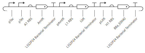
This yields the following circuit:
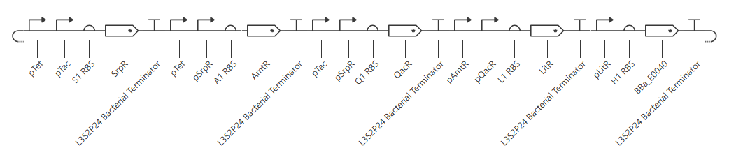
Expected outcome:
| aTc | IPTG | SrpR | AmtR | QacR | LitR | Output |
|---|---|---|---|---|---|---|
| 0 | 0 | 0 | 1 | 1 | 0 | 1 |
| 1 | 0 | 1 | 1 | 0 | 1 | 0 |
| 0 | 1 | 1 | 0 | 1 | 1 | 0 |
| 1 | 1 | 1 | 1 | 1 | 0 | 1 |
This is the opposite of an XOR gate (yielding output at Neither input or Both inputs, rather than yielding output at Either of only one input), so i just need to add one more layer of repressible promoter to get what I’m hoping for I think. Or I can replace the LitR with GFP and remove the section with GFP under pLitR.
New circuit for XOR gate:
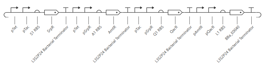
Expected outcome:
| aTc | IPTG | SrpR | AmtR | QacR | Output |
|---|---|---|---|---|---|
| 0 | 0 | 0 | 1 | 1 | 0 |
| 1 | 0 | 1 | 1 | 0 | 1 |
| 0 | 1 | 1 | 0 | 1 | 1 |
| 1 | 1 | 1 | 1 | 1 | 0 |
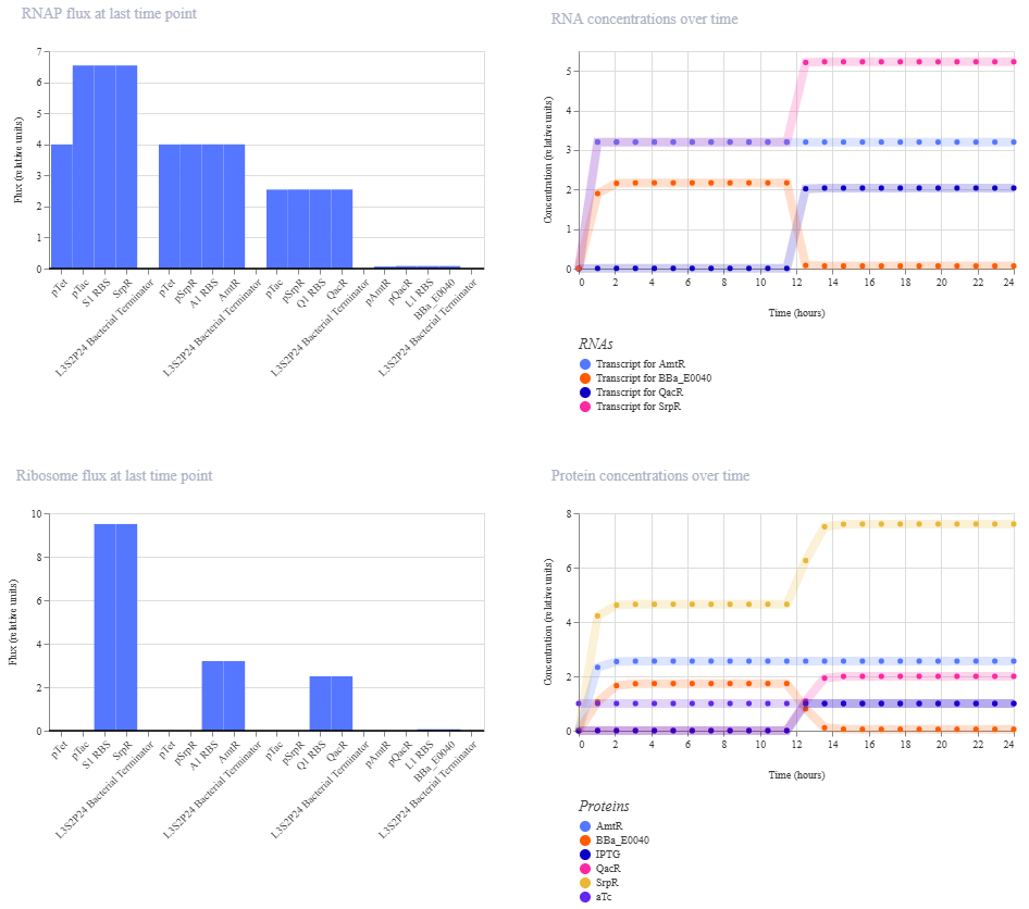
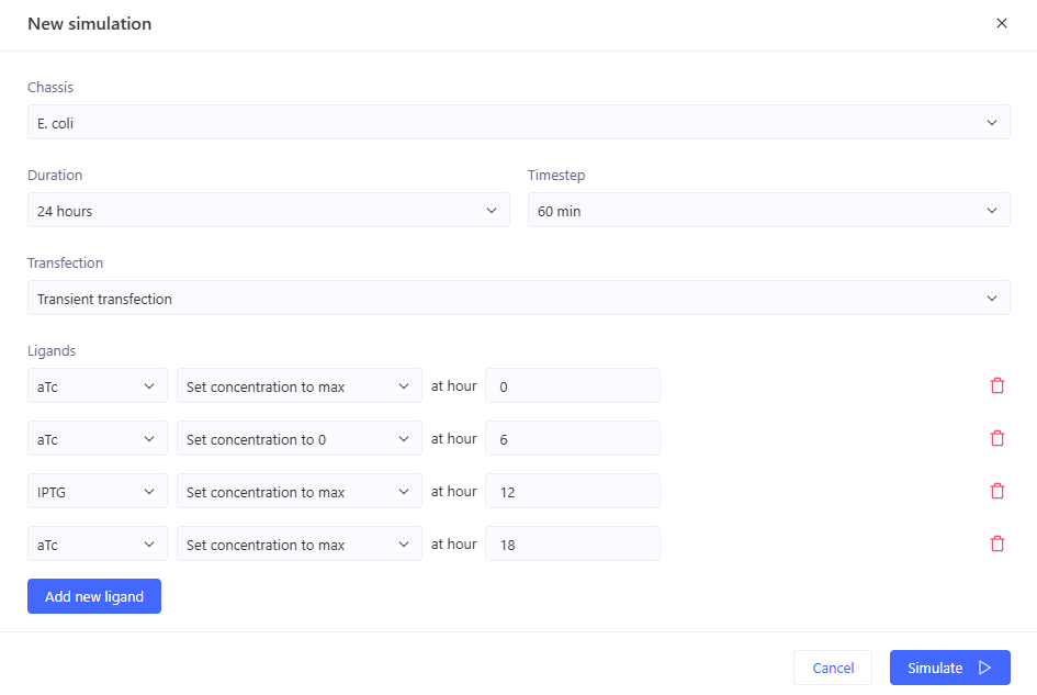
Simulation:
0-6 hrs: aTc only
6-12 hrs: nothing
12-18 hrs: IPTG only
18-24 hrs: aTc and IPTG
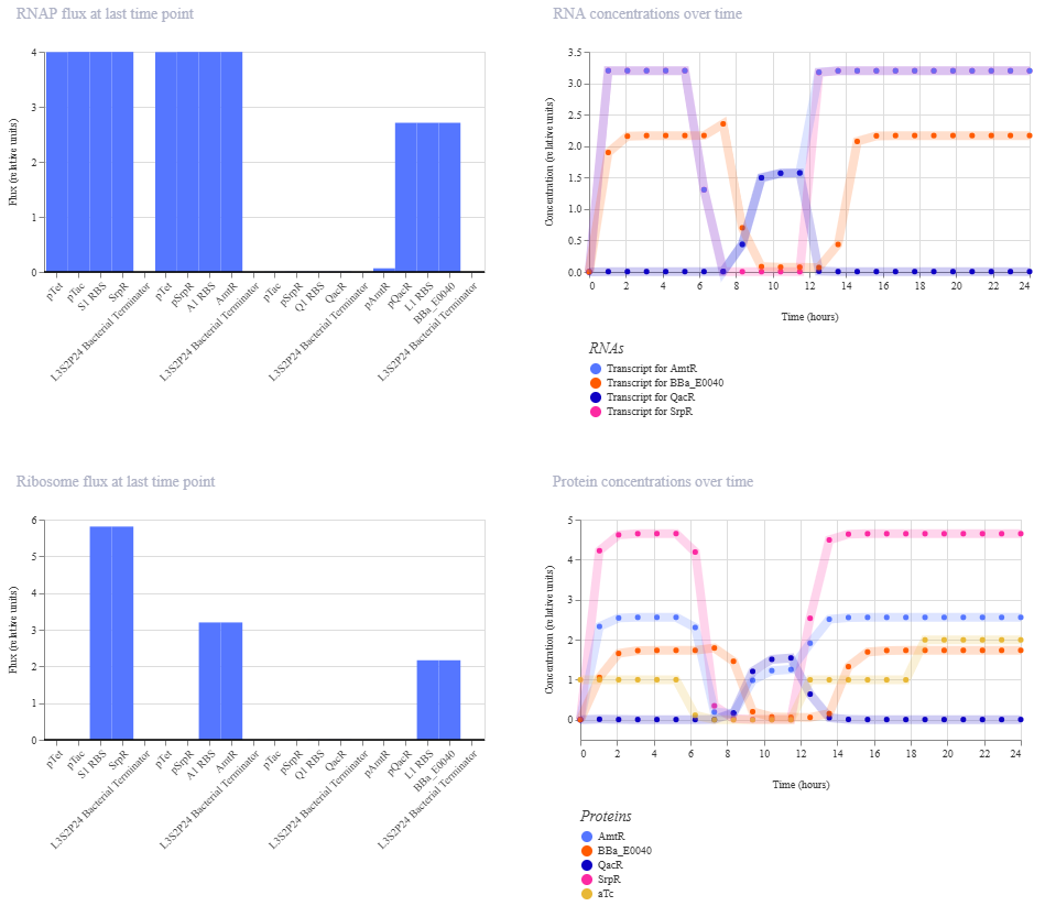 This did not give the expected outcome. GFP doesn’t fall again at the end like it should.
I think there was just something with the simulation; either i didn’t set up the ligands properly, or it wasn’t enough time to equilibrate or something. Because when I run the different ligand combinations individually, or just one change over 24 hours it works like expected.
Here is the outcome for aTc high the entire time, and adding high IPTG at 12 hours. So it does work as expected.