Week 7 Lab: Neuromorphic Circuits
We started off our node’s discussion of the neuromorphic circuits based off of a couple example circuits developed by TA Steven with help from ClaudeAI. Because I feel like I don’t really understand the analog vs binary computing, I was most interested in the design that explored that aspect.
Option C: Competing Inhibitors Concept: One dominant ERN (CasE, high dose) controls the whole network. It kills both Csy4 and the green output directly.
CasE (strong) ──kills──▶ Csy4 (weak, dies)
──kills──▶ mNeonGreen (green, OFF)Csy4 (dead) ──can’t kill──▶ PgU (survives, but has nothing to do)
Group Plasmid Amount Role X1 CasE 200 ng Dominant enzyme X1 eBFP2 50 ng Blue control light X2 Csy4_rec_CasE 100 ng Csy4, killed by CasE X2 mMaroon1 50 ng Maroon control light X3 PgU_rec_Csy4 100 ng PgU, freed because Csy4 is dead Bias CasE_rec_mNeonGreen 150 ng Green, killed by CasE Expected result: Blue ON, Maroon ON, Green OFF Why it’s interesting: Shows that dosage (ng amounts) determines who wins. You could run a second experiment with CasE reduced to 50 ng to see if the outcome changes — demonstrating the analog nature of the circuit.
Worth noting that there was significant confusion over the way that Claude worded the “Roles” of the Enzyme_rec_output constructs. The correct interpretation is as follows: CasE_rec_mNeonGreen means that the plasmid encodes for mNeonGreen with a recognition site for CasE (therefore, it is amount of mNeonGreen minus amount of CasE to determine if fluorescent green is present).
I was interested in the analog/dosing aspect of this circuit, but I thought it might be more interesting to include a different color, so we would see either Green or a different fluorescence, depending on which enzyme there was more of.
My first attempt looked like this:
| Circuit Name | Transfection Group | Contents | Concentration (ng/ul) | DNA wanted (ng) |
|---|---|---|---|---|
| JKScircuit-1 | X1 | PgU | 50 | 200 |
| JKScircuit-1 | X1 | eBFP2 | 50 | 100 |
| JKScircuit-1 | X2 | PgU_rec_Csy4 | 50 | 50 |
| JKScircuit-1 | X2 | mMaroon1 | 50 | 100 |
| JKScircuit-1 | Bias | PgU_rec_mNeonGreen | 50 | 100 |
| JKScircuit-1 | Bias | CasE_rec_Csy4_rec_mKO2 | 50 | 100 |
I figured that if there was more PgU than Csy4, then it would output orange. But if there was more Csy4 than PgU then it would output green. This is because PgU subtracts from mNeonGreen output, Csy4 subtracts from mKO2 output, and PgU subtracts from Csy4 output. So if there is high PgU, then mNeonGreen is not expressed; there is not enough Csy4 to compete with the PgU, and since there is not Csy4, there is nothing to inhibit the mKO2 output. If there is high Csy4, then there is not enough PgU to inhibit mNeonGreen (because it is mostly used up in competing with Csy4), and the remaining Csy4 inhibits mKO2. I figured that since I don’t have any CasE expressed in my system, it doesn’t matter that CasE could also inhibit mKO2. eBBFP2 and mMaroon1 are controls to check for transfection efficiency. I had the unbalanced DNA amounts because that tests the analog computing that I was interested in.
Unfortunately, this first attempt gave an error when I tried to put it into the Neuromorphic Wizard tool. Looking through our forum discussion post, I was able to somewhat troubleshoot off of this explanation TA Steven got from ClaudeAI when he was trying to troubleshoot Jessica Wu’s circuit:
Why it failed:
- The Predict API only accepts X1 + X2 groups (no OR, NOT, Bias etc.)
- Each group must have exactly: marker + ERN + ERN_rec_output
Based off this, I changed the Transfection Group for the last two lines from Bias to X1 or X2; because even though that’s what was in the example given in the lab, this suggested that the Neuromorphic Wizard API could only accept X1 and X2. So my second attempt looked like this:
| Circuit Name | Transfection Group | Contents | Concentration (ng/ul) | DNA wanted (ng) |
|---|---|---|---|---|
| JKScircuit-2 | X1 | PgU | 50 | 200 |
| JKScircuit-2 | X1 | eBFP2 | 50 | 100 |
| JKScircuit-2 | X2 | PgU_rec_Csy4 | 50 | 50 |
| JKScircuit-2 | X2 | mMaroon1 | 50 | 100 |
| JKScircuit-2 | X2 | PgU_rec_mNeonGreen | 50 | 100 |
| JKScircuit-2 | X1 | CasE_rec_Csy4_rec_mKO2 | 50 | 100 |
Unfortunately, this still gave an error. I suspect that the PgU_rec_Csy4 and PgU_rec_mNeonGreen being in the same transfection group is outside the bounds of what the API could accept, but biologically, I don’t think this would be a problem. Essentially, I am using PgU_rec_Csy4 as an ERN instead of as a ERN_rec_output. The proper solution is probably to instead put PgU_rec_mNeonGreen into an X3 group instead of in X2 with the PgU_rec_Csy4, but we didn’t have enough colors to use as transfection controls since I wanted to use two colors as outputs.
TA Steven put my circuit into ClaudeAI to troubleshoot as well, and gave me this feedback:
Fixed. Here’s what changed:
Original Fixed Why X2: PgU_rec_Csy4 (output, no ERN) X2: Csy4 (ERN) X2 needs a standalone ERN X2: mMaroon1 X2: mKO2 API only recognizes eBFP2/mKO2 as markers X1: CasE_rec_Csy4_rec_mKO2 X1: Csy4_rec_mNeonGreen No CasE source existed; output should be mNeonGreen X2: PgU_rec_mNeonGreen kept Valid output, inhibited by PgU from X1 Circuit logic: PgU (X1, 200ng) ────inhibits────▶ PgU_rec_mNeonGreen (X2)
Csy4 (X2, 50ng) ────inhibits────▶ Csy4_rec_mNeonGreen (X1)This is an asymmetric cross-inhibition — PgU is dosed 4x heavier than Csy4, so X1 should dominate the competition. The heatmap should show stronger suppression along the X1 axis. Total DNA: 600ng (under limit).
This is frustrating because I’m pretty sure this is a limitation of the Neuromorphic Wizard API, and my circuit is biologically sound. The first one is what I suggested originally, that I am using PgU_rec_Csy4 as an ERN instead of as a ERN_rec_output. I’m not sure why X2 needs a standalone ERN. The second one is just that it doesn’t accept mMaroon1 as a marker, which is odd because it’s listed on the Parts list as an option. The third one is what I explained earlier; that since I don’t have any CasE expressed in my system, it doesn’t matter that CasE could also inhibit mKO2.
While I would have liked to see experimentally what would happen with my design, since I do think it’s valid biologically, we wanted to submit validated circuits only, since each node could only submit two circuits. So TA Steven submitted my circuit that was fixed by Claude because it was able to give a valid output on the Predict tab of the Neuromorphic Wizard.
Results:
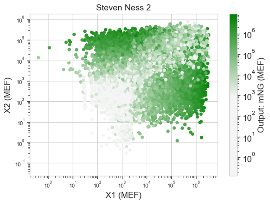
I’m honestly not sure if this shows what I’d expect. I’m unclear on what these heatmaps are actually showing. Like I know that each dot is a cell that was transfected with the same things, but I’m not sure what exactly that means in regards to my circuit. I think I probably need to rewatch the lecture for clarity.