This week’s experiment was done late at night. To speed things up, we tried to simplify several steps in the protocol and cut a few corners, such as filtering only once when the protocol called for two rounds of filtration. In the end, we did not get the result we were hoping for. The plates only showed some unidentified white colonies, possibly E. coli, but the issue is that the original E. coli we used was supposed to be purple.
This week, I worked on designing a small genetic circuit system based on RNA endonucleases and fluorescent protein outputs. Instead of starting directly from a final circuit, we first organized the available biological parts and tried to understand how they could be connected into a regulatory network.
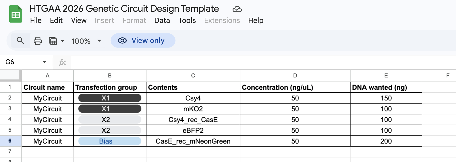
Organizing the Basic Parts We started by making a spreadsheet of possible genetic circuit part names. The first group of parts was the RNA endonucleases, or ERNs:
This week’s Lab work is effectively part of this week’s Homework;
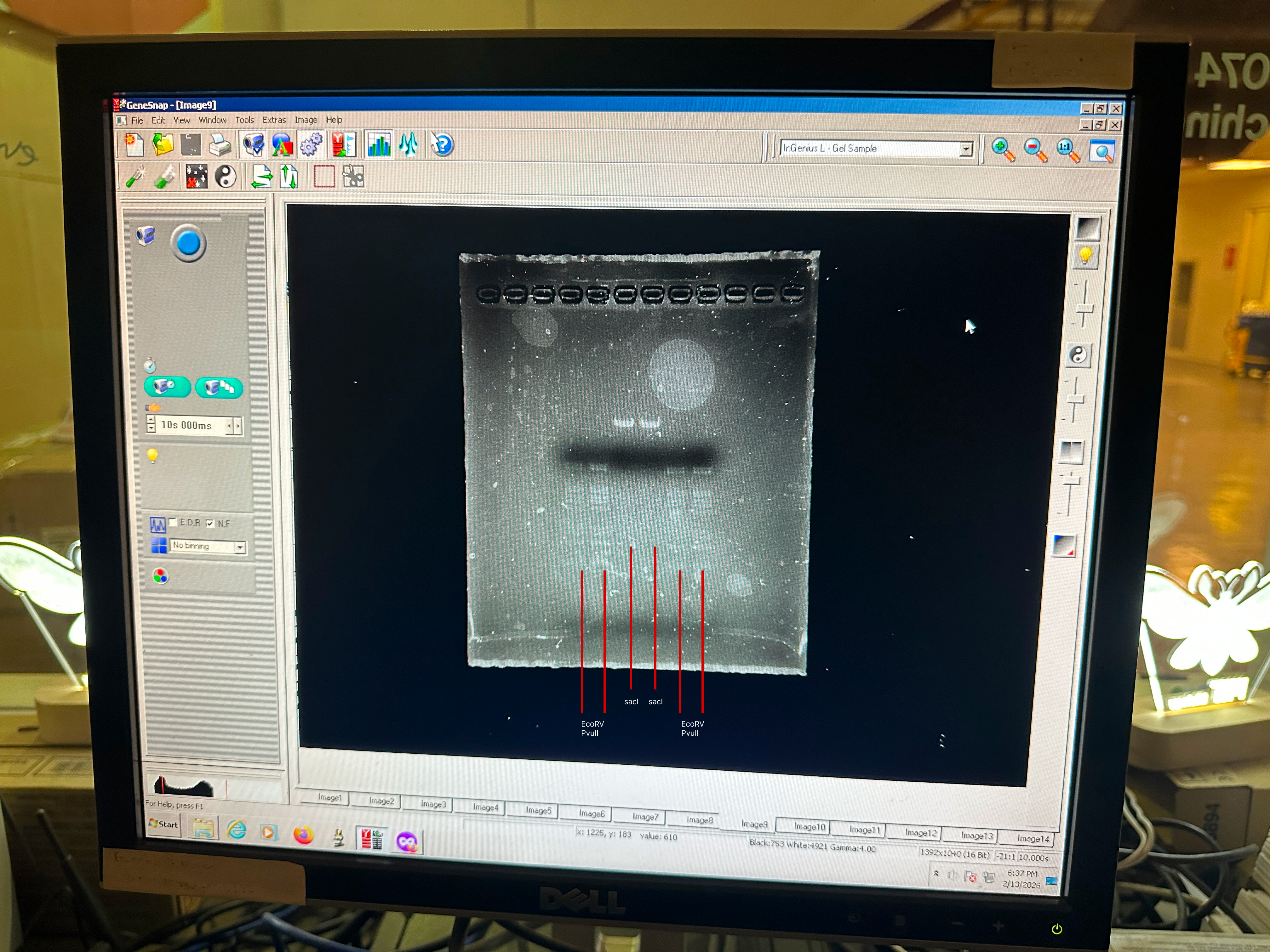
Week 5_Lab: Protein Design Part II
This week’s Lab work is effectively part of this week’s Homework;
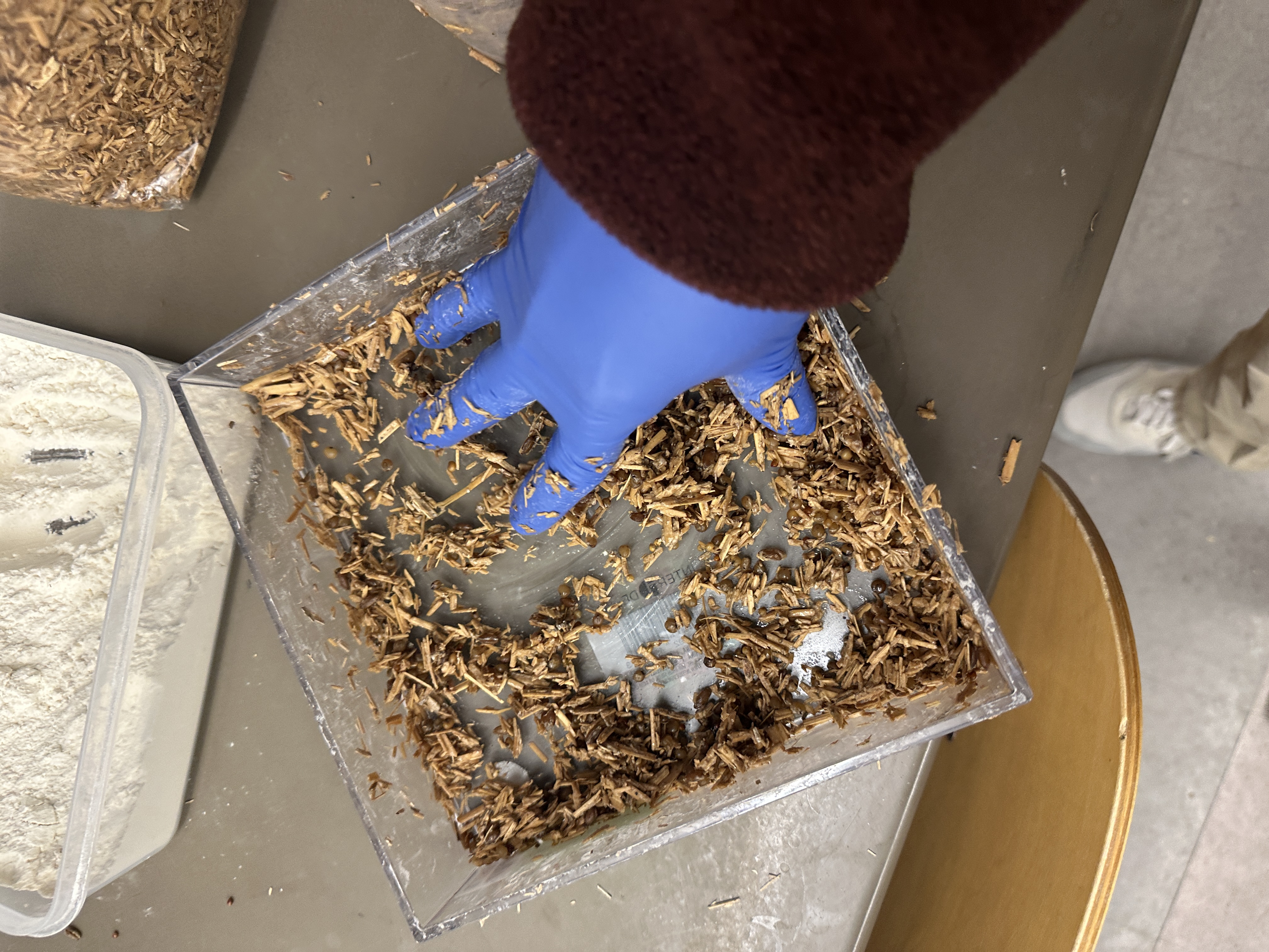
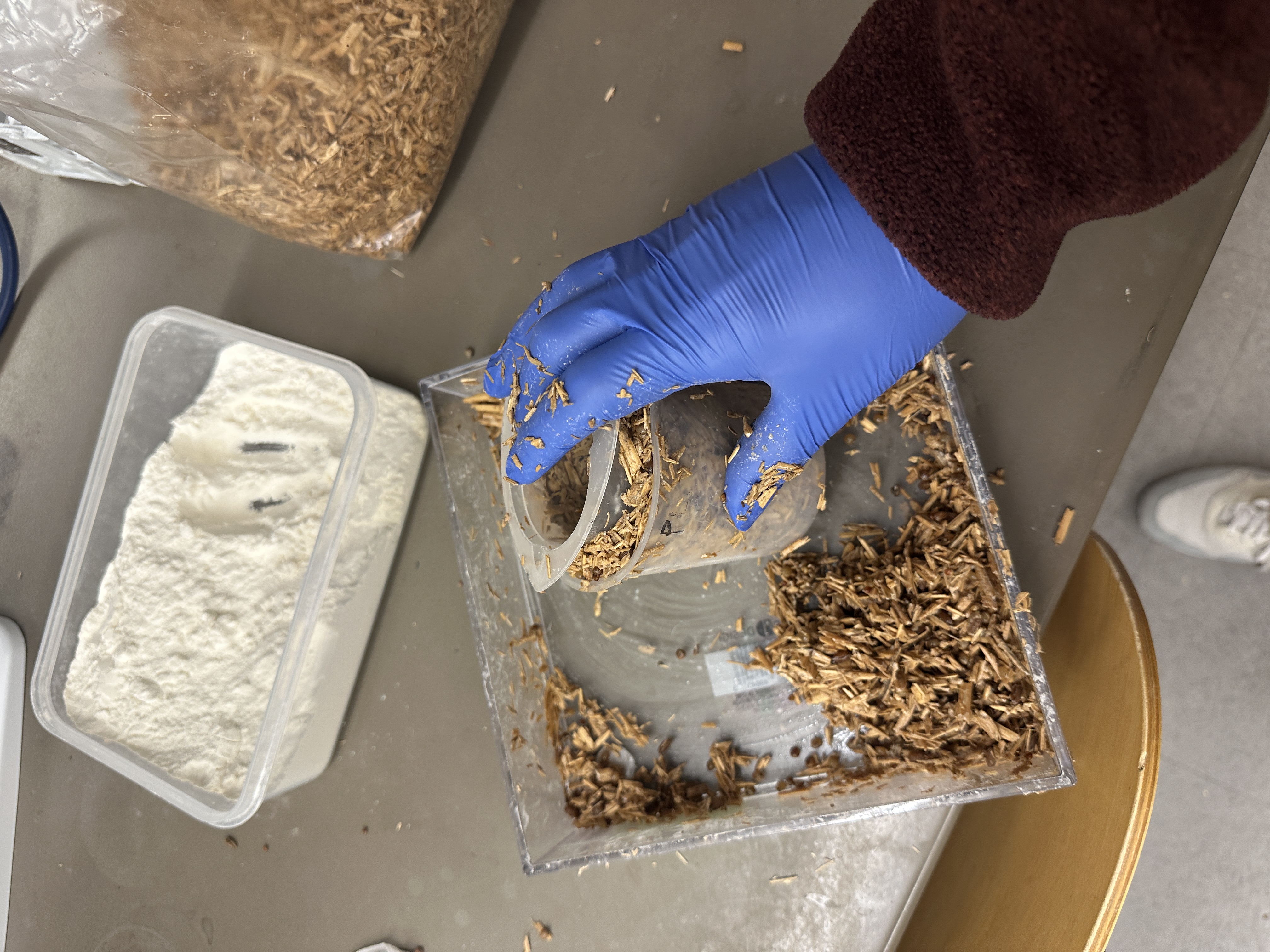
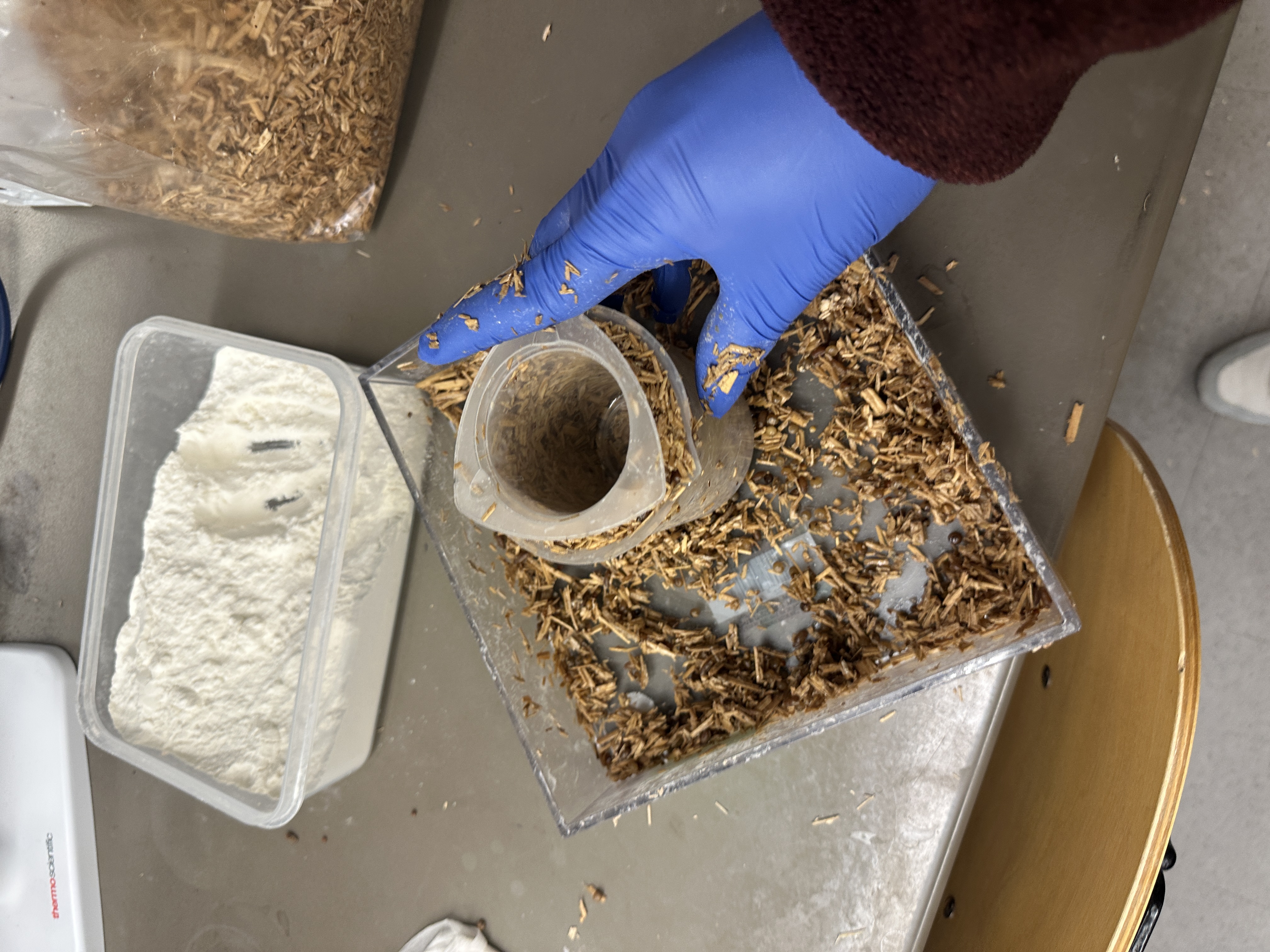
Week 6_Lab: Gibson Assembly
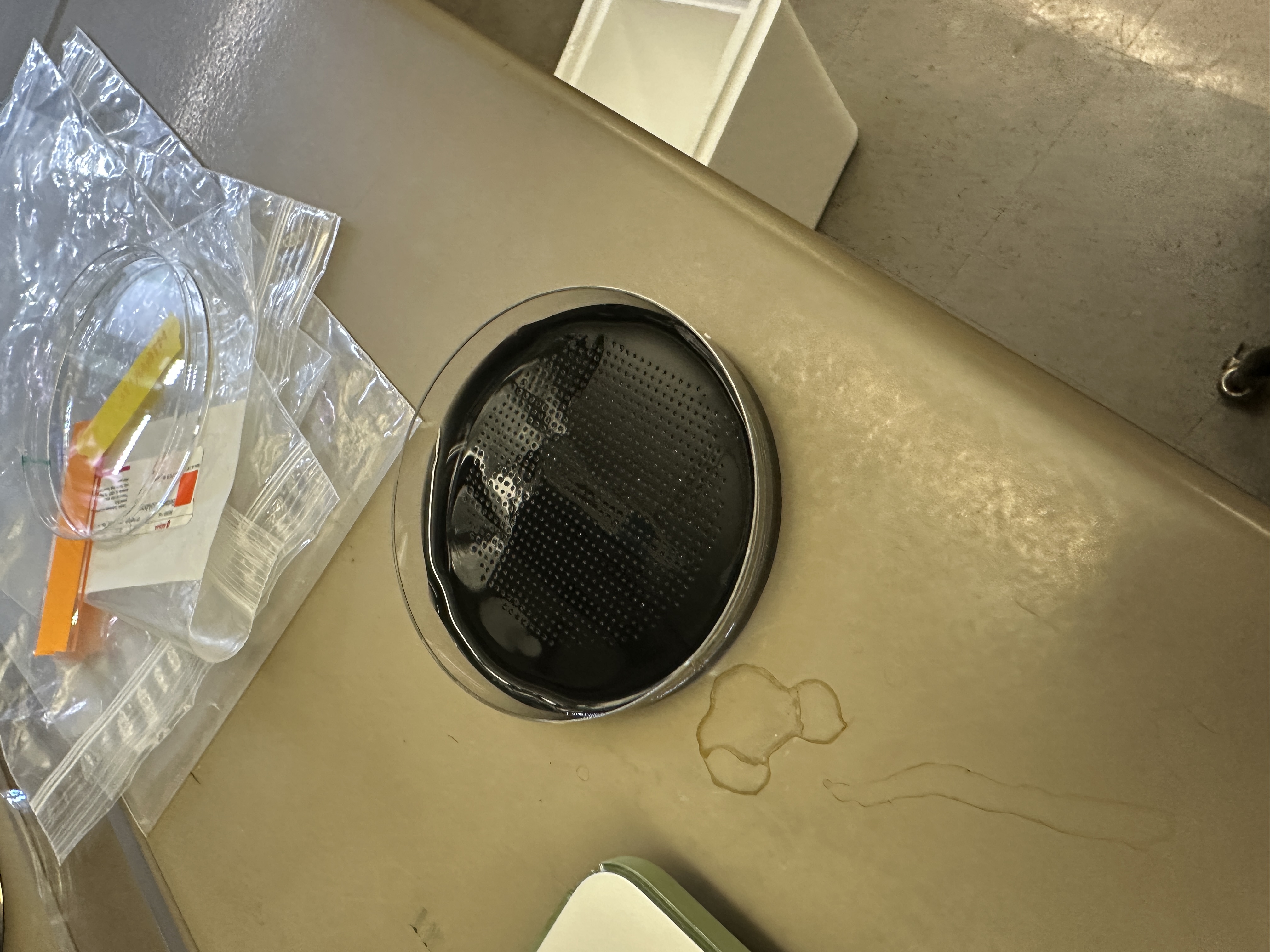
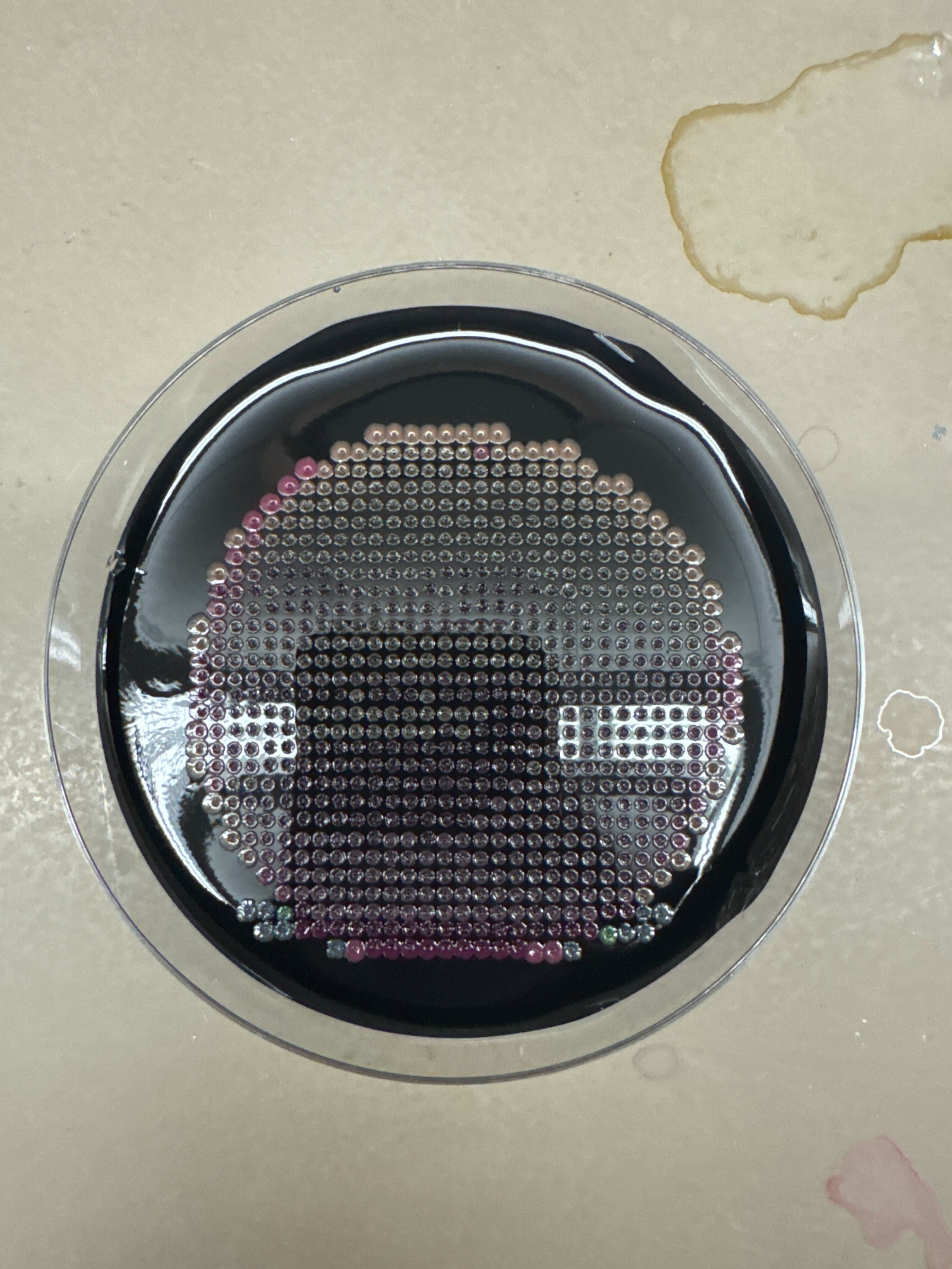
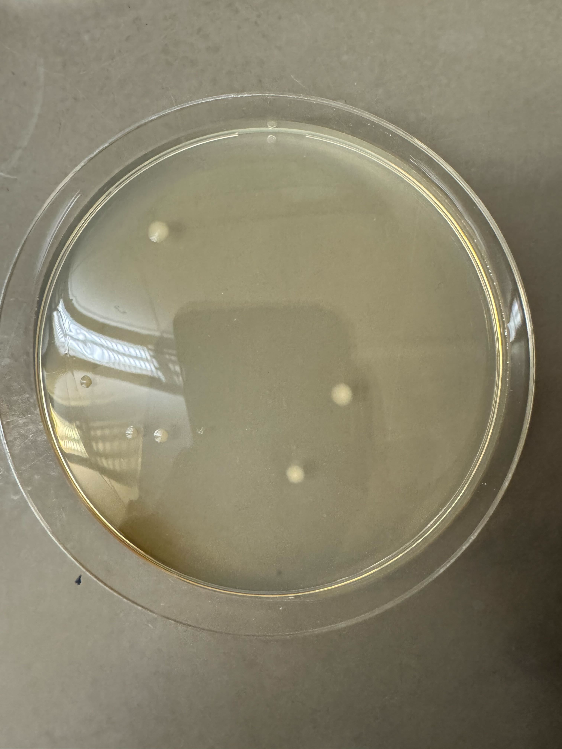
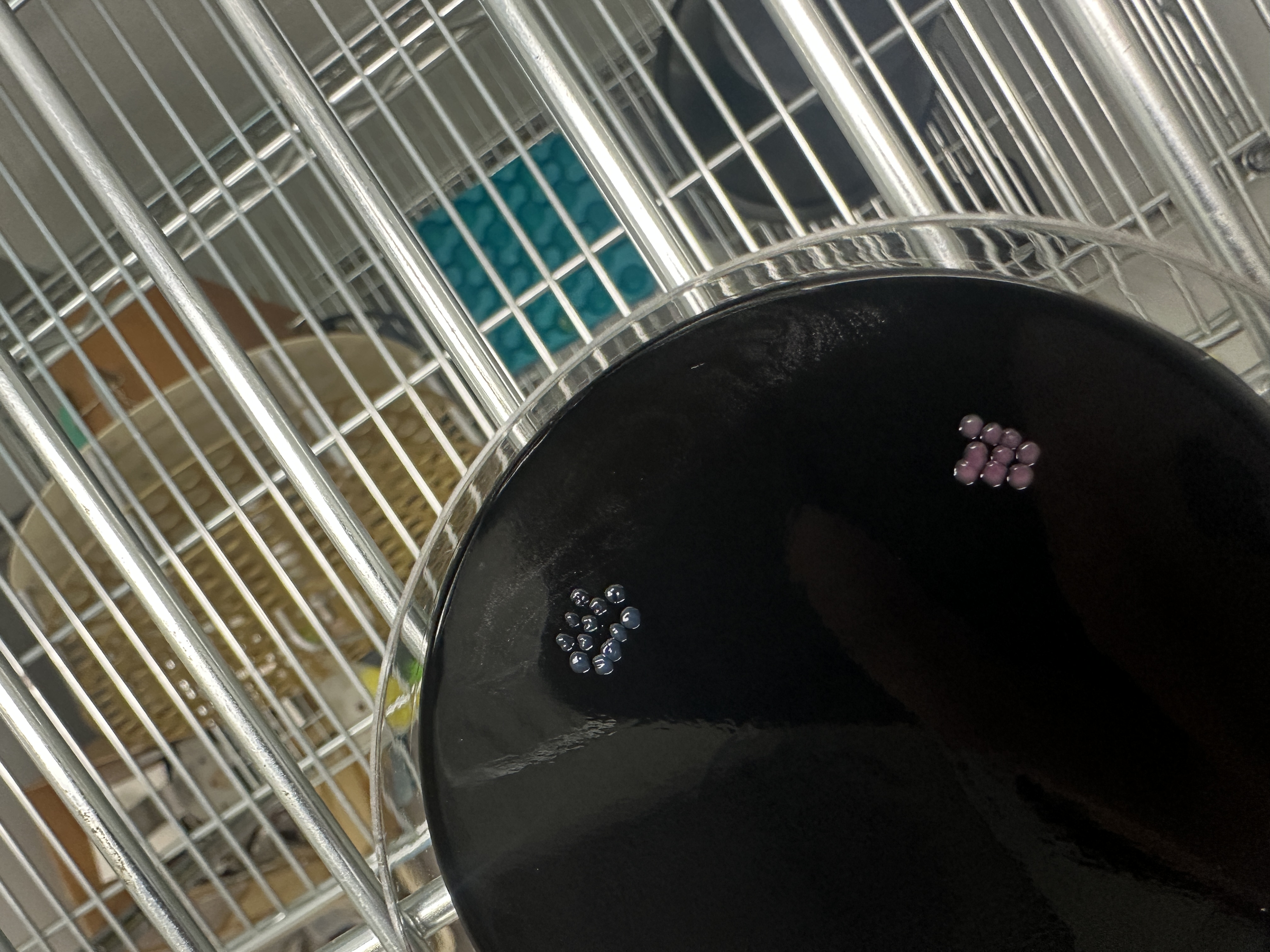
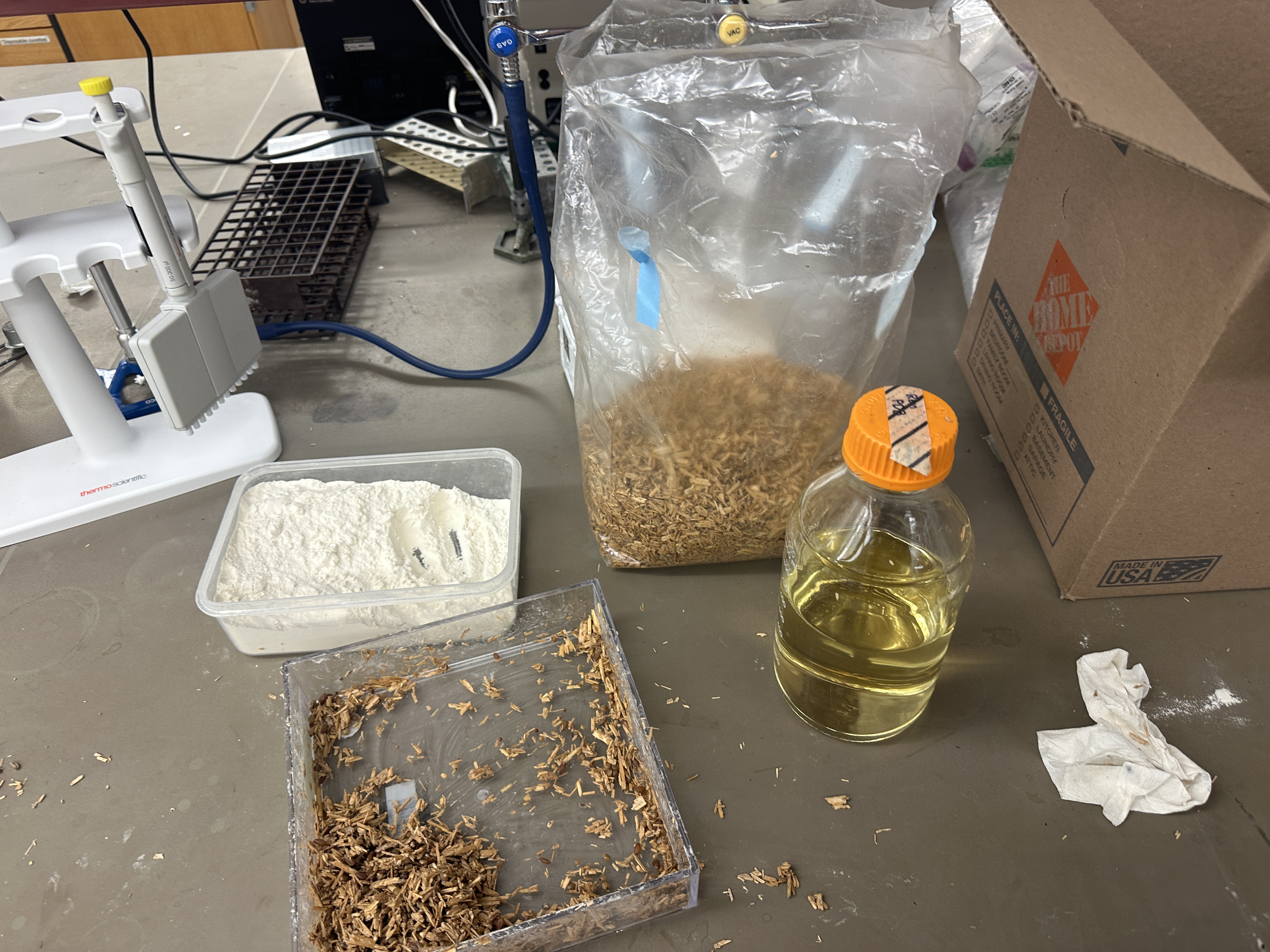
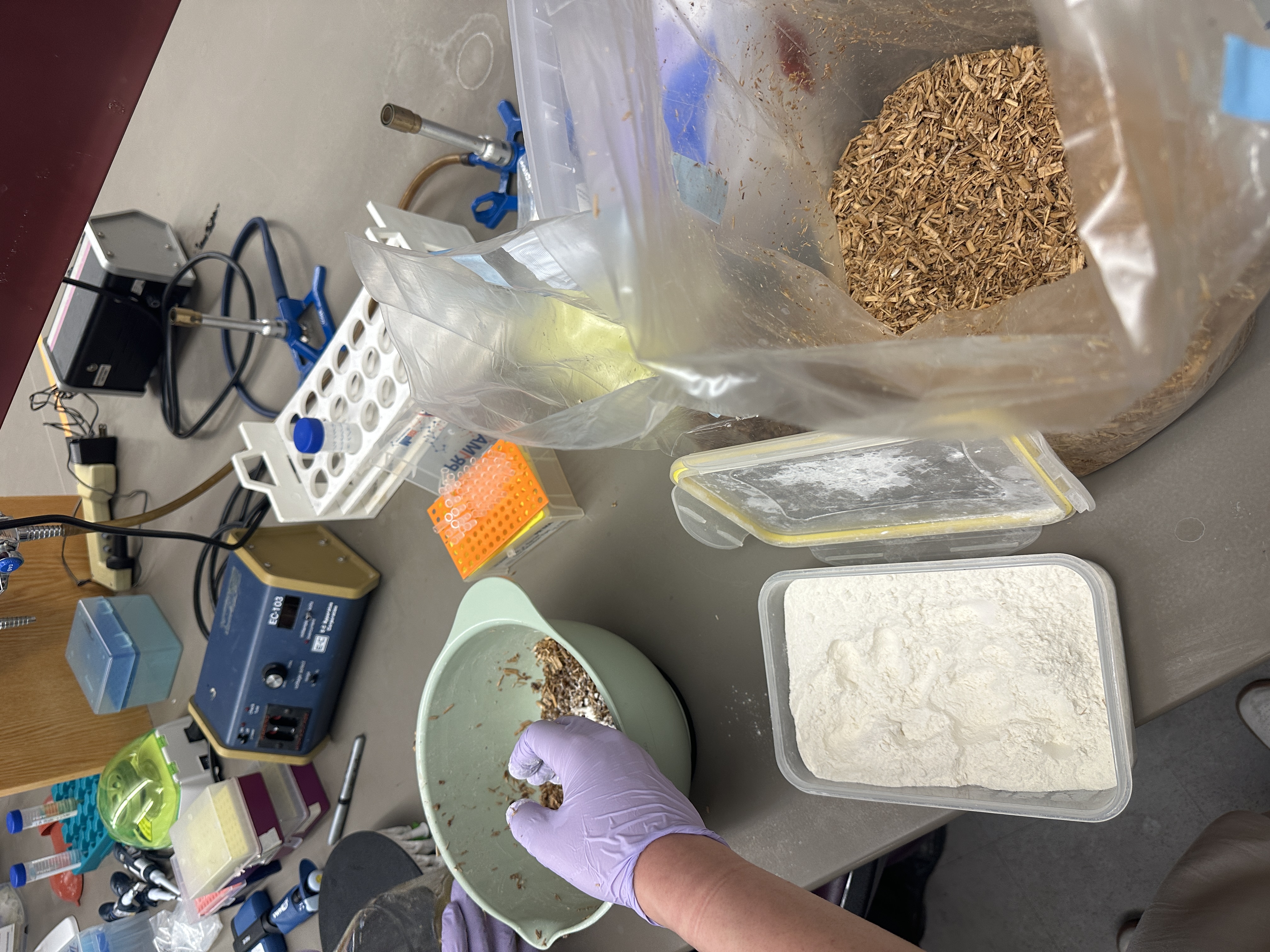
This week’s experiment was done late at night. To speed things up, we tried to simplify several steps in the protocol and cut a few corners, such as filtering only once when the protocol called for two rounds of filtration. In the end, we did not get the result we were hoping for. The plates only showed some unidentified white colonies, possibly E. coli, but the issue is that the original E. coli we used was supposed to be purple.
So we took some samples from another group and tried again. This time, they grew successfully, which suggests that the problem most likely came from the way we modified or skipped parts of the protocol during the workflow.
Week 7_Lab: Neuromorphic Circuits
This week, I worked on designing a small genetic circuit system based on RNA endonucleases and fluorescent protein outputs. Instead of starting directly from a final circuit, we first organized the available biological parts and tried to understand how they could be connected into a regulatory network.
1. Organizing the Basic Parts
We started by making a spreadsheet of possible genetic circuit part names. The first group of parts was the RNA endonucleases, or ERNs:
CasE
Csy4
PgU
These ERNs can recognize specific RNA sequences and cut or regulate transcripts that contain their recognition sites. This made them useful as regulatory components in the circuit.
We also listed several fluorescent proteins as possible outputs:
mKO2
eBFP2
mMaroon1
mNeonGreen
These fluorescent proteins would allow us to visually read out the behavior of the circuit.
2. Building a Naming System
After listing the basic parts, we created a naming rule to describe how one part regulates another:
ERN_rec_target
In this naming system, rec means that the target transcript contains the recognition site for a specific ERN.
For example:
PgU_rec_Csy4
This means that the Csy4 transcript contains a PgU recognition site. If PgU is expressed, it can recognize and regulate the Csy4 mRNA.
This naming system helped us describe different circuit connections clearly and consistently.
3. Designing ERN-to-ERN Regulation
Next, we used the naming rule to generate possible regulatory connections between the ERNs:
PgU_rec_Csy4
PgU_rec_CasE
Csy4_rec_CasE
CasE_rec_Csy4
These parts describe cases where one ERN controls the expression of another ERN. This creates the possibility of building layered regulatory circuits, where one RNA-processing enzyme affects another regulatory node.
At this stage, I was trying to think of the circuit less as a single linear pathway and more as a small network of interacting regulatory parts.
4. Connecting ERNs to Fluorescent Outputs
After that, we connected the ERNs to fluorescent protein outputs. We listed several possible reporter constructs:
Csy4_rec_mNeonGreen
CasE_rec_mNeonGreen
PgU_rec_mNeonGreen
CasE_rec_Csy4_rec_mKO2
The first three designs are simpler reporter outputs. For example, Csy4_rec_mNeonGreen means that the mNeonGreen transcript contains a Csy4 recognition site, so Csy4 can regulate the final green fluorescence output.
The last design, CasE_rec_Csy4_rec_mKO2, is more complex because it includes more than one regulatory recognition site. This suggests that the final mKO2 output could be controlled by multiple ERN-related inputs.
5. Sketching the Circuit Logic
Once the parts were organized, we began drawing the circuit logic. The goal was to show how the ERNs could regulate each other and how those regulatory relationships could eventually control fluorescent protein expression.
The general logic was:
Input / ERN expression
        ↓
ERN recognizes specific RNA site
        ↓
Target transcript is regulated
        ↓
Fluorescent protein output changes
For example, if Csy4 is present and the mNeonGreen transcript contains a Csy4 recognition site, then Csy4 can affect the amount of mNeonGreen that is produced. The final fluorescence becomes a readout of the regulatory interaction.
6. What I Learned from This Process
Through this process, I learned that designing a genetic circuit is not only about choosing biological parts, but also about defining clear relationships between them. The spreadsheet helped me organize the parts as modular components, while the circuit diagram helped me understand how those components could interact.
I also realized that the naming system is important because it makes the design easier to read, discuss, and modify. Once we had a consistent structure like ERN_rec_target, it became much easier to generate new circuit possibilities and compare them.
Overall, this exercise helped me understand how RNA endonucleases such as Csy4, CasE, and PgU can be used as programmable regulatory elements in a genetic circuit. By connecting them to fluorescent protein reporters, we could design circuits where the output is visible and experimentally testable.
ERN_rec_target
Week 8_Lab:
NO LAB THIS WEEK
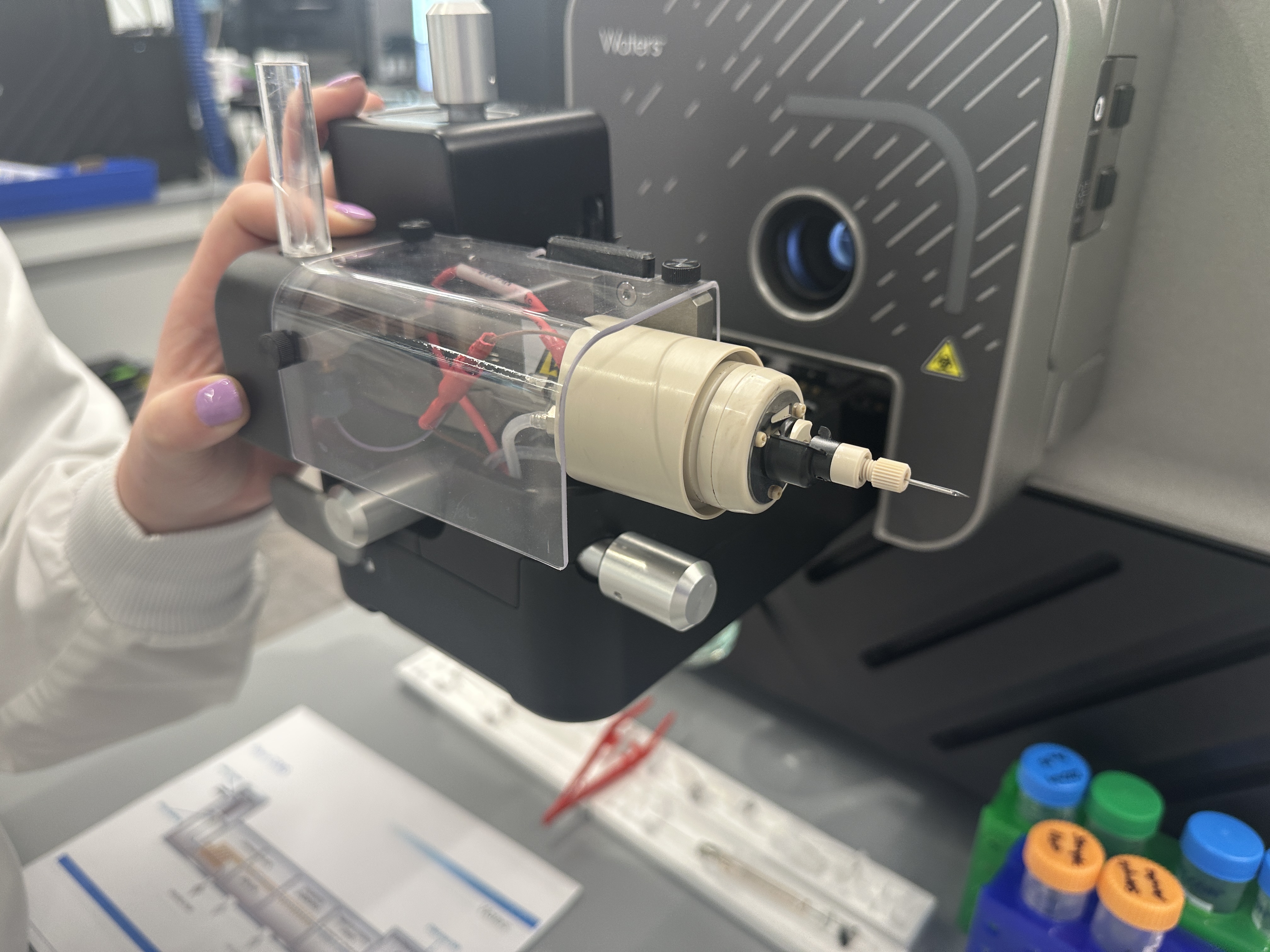
Week 9_Lab: Cell Free
Protein Purification (LOA this week, moved lab to final week)