Week 7 Lab : Genetic Circuits Part II: Neuromorphic Circuits
This week’s lab had a dry and wet component. As a Global Comitted Listener without lab access, I was excused from the wetlab component. I joined for the dry component over which were were allowed to work as a team. That said, what follows are snapshots of our work. The focus was the building of our own IANN.
Pre-Lab | Overview
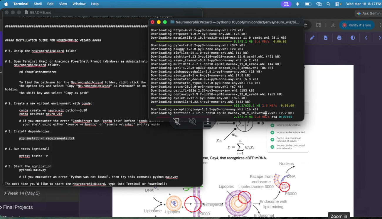
Download Neuromorphic Wizard: download this folder NeuromorphicWizard onto your machine by clicking “Download all” in the upper right. Follow the instructions in ‘README.md’ for a step-by-step installation guide.
Familiarize yourself with the concepts behind each component of the lab: 1) how endoribonucleases can be used to perform arithmetic inside of cells and 2) how Lipofectamine 3000 works to transfect plasmids into human cells.
Done.
Overview | Background
In this two-day lab, you will design and build your very own IANN using a library of plasmids from the Ron Weiss lab and human embryonic kidney (HEK) 293 cells. IANNs differ from traditional synthetic genetic circuits because IANNs can perform analog computations, rather than being limited to digital computations. IANNs are also universal function approximators–given an adequate number of intracellular artificial neurons, you can use an IANN to achieve any input/output behavior you’d like.
Acknoweledged.
Overview | Concepts Learned & Skills Gained
This is a lab with a dry and wet component. In the dry lab component, you will design a neuromorphic circuit in groups of 3. Once your design has been finalized, you will write instructions for an OT-2 to build your circuit for you. In the wet lab component, a TA will upload your OT-2 instructions and you will observe the OT-2 building and transfecting your IANN into HEK293 cells.
Acknoweledged.
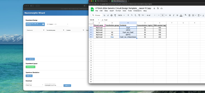
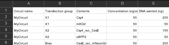
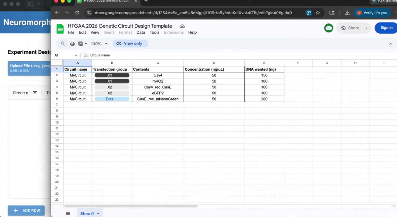
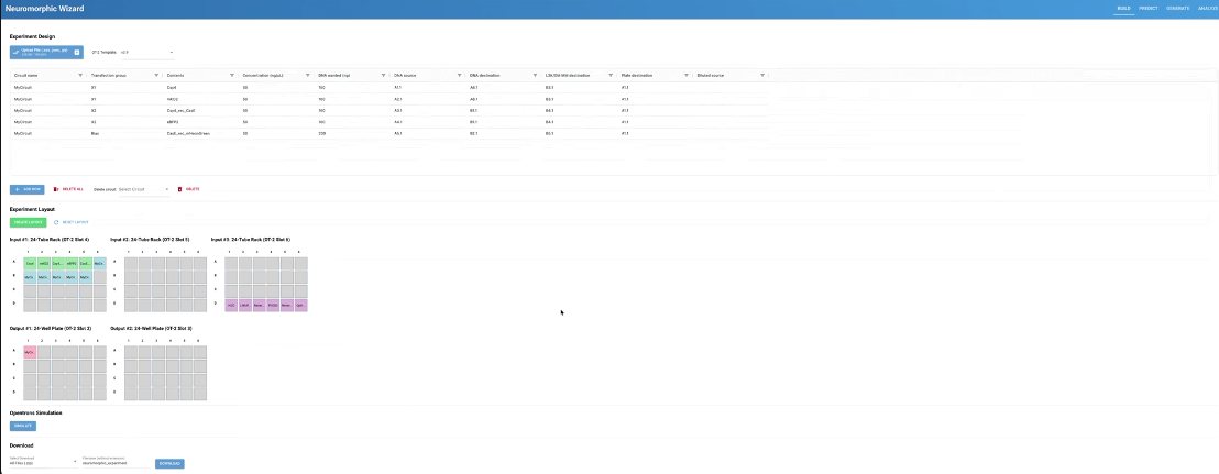
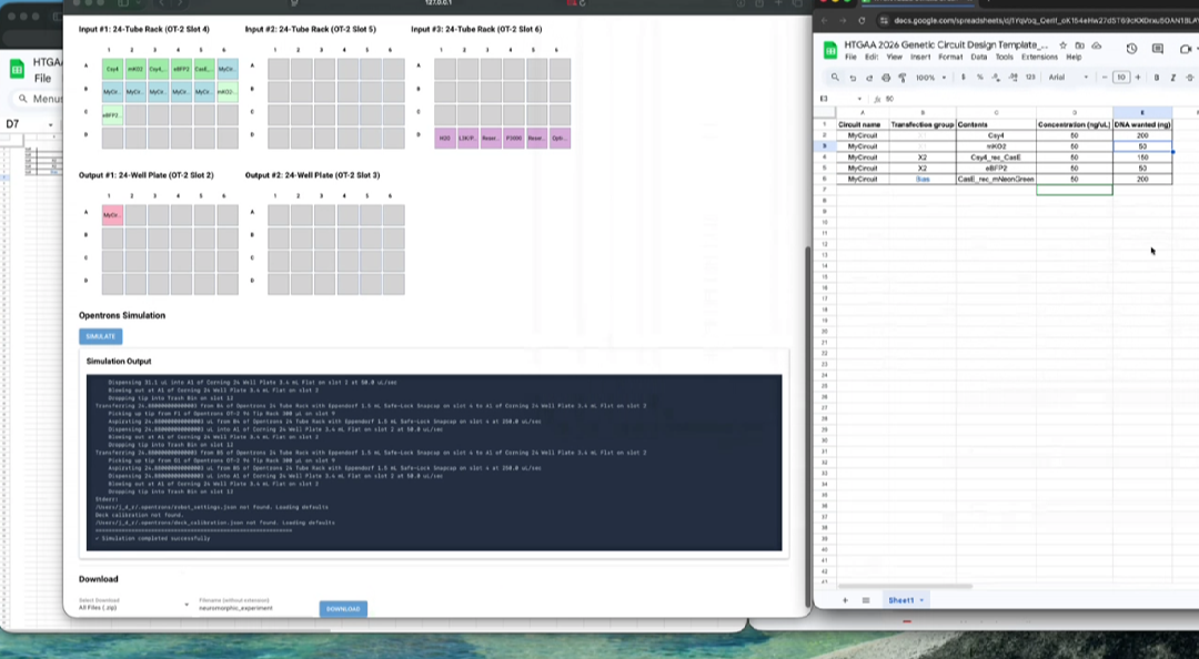
The Pre-lab involved us setting up and understanding Neuromorphic Wizard. We wrote instructions using this template (https://www.google.com/url?q=https://docs.google.com/spreadsheets/d/12S4Vv6e_am6U6dMgpijt1G9rtoRyfcdoKdIXvnkdGTo/edit?usp%3Dsharing&sa=D&source=editors&ust=1774224628668116&usg=AOvVaw2ayNzuuoVfm9mQYCP30sjK) and using these names (https://www.google.com/url?q=https://docs.google.com/spreadsheets/d/1cyEgmj08P40iUE5KOdvn_oaDhB7sOkQJwA7900rDqMc/edit?usp%3Dsharing&sa=D&source=editors&ust=1774224628668584&usg=AOvVaw3_lcXglYGq-h7wgkIkT-Tx).
After we entered our circuit into a google form.
Our Members were: Jason Ross, Nana Agyei, and Xavier Palmer. Jason served as the project submitter.
Pictures of aspects of the process can be found below.
Esssentially, we installed Neuromorphic Wizard, used the template, and generated outputs, before submitting our project.
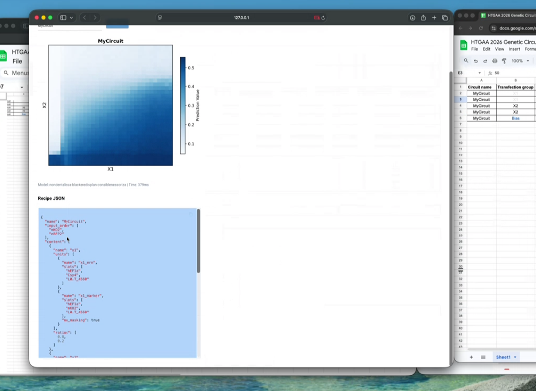
The code below the graph is:
{ “name”: “MyCircuit”, “input_order”: [ “mKO2”, “eBFP2” ], “content”: [ { “name”: “x1”, “units”: [ { “name”: “x1_ern”, “slots”: [ “hEF1a”, “Csy4”, “L0.T_4560” ] }, { “name”: “x1_marker”, “slots”: [ “hEF1a”, “mKO2”, “L0.T_4560” ], “no_masking”: true } ], “ratios”: [ 0.8, 0.2 ] }, { “name”: “x2”, “units”: [ { “name”: “x2_output”, “slots”: [ “hEF1a”, “Csy4_rec”, “CasE”, “L0.T_4560” ] },
{ “name”: “x2_marker”, “slots”: [ “hEF1a”, “eBFP2”, “L0.T_4560” ], “no_masking”: true } ], “ratios”: [ 0.75, 0.25 ] }, { “name”: “bias”, “units”: [ { “name”: “bias_output”, “slots”: [ “hEF1a”, “CasE_rec”, “mNeonGreen”, “L0.T_4560” ] } ], “ratios”: [ 1.0 ] } ] }
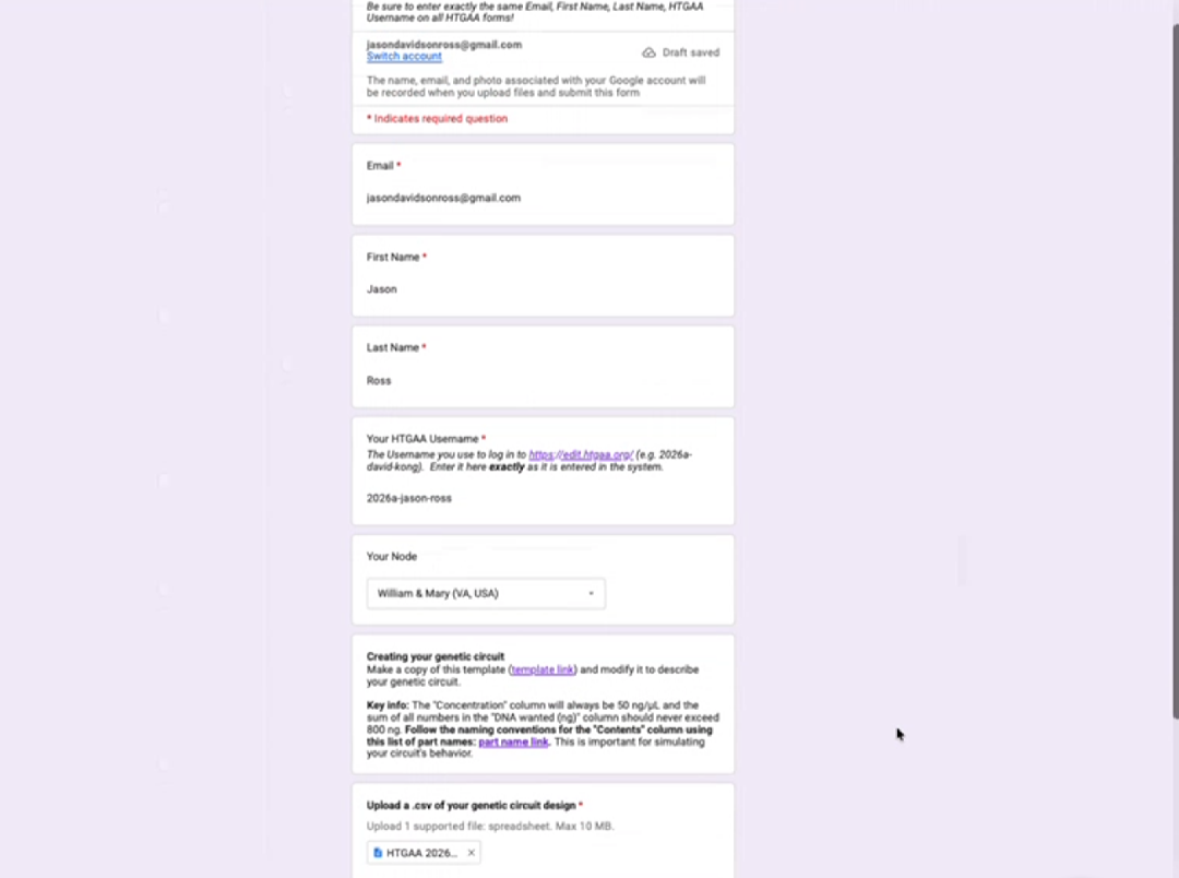
Above is a snapshot of the google form submitted by Jason Ross. His page can be reviewed for more project details and progress.