Week 6: Genetic Circuit Part I
DNA Assembly
Q1. What are some components in the Phusion High-Fidelity PCR Master Mix and what is their purpose?
Phusion Master Mix contains Phusion DNA Polymerase, which has 3’ to 5’ proofreading exonuclease activity that corrects misincorporated bases, with a much lower error rate than standard Taq polymerase. dNTPs are the substrate for new strand synthesis. A reaction buffer maintains optimal pH and ionic conditions, and includes MgCl₂ as a required cofactor for polymerase function and primer binding.
Q2. What are some factors that determine primer annealing temperature during PCR?
Annealing temperature is primarily set by the primer melting temperature. Longer primers have a higher melting temperature because more base pairs stabilize binding. Higher GC content raises the temperature because GC pairs form three hydrogen bonds versus two for AT pairs, which requires more energy to break.
Q3. Compare and contrast PCR and restriction enzyme digests.
PCR makes copies of a DNA fragment, and works on any sequence because the primers are designed to control what the ends of the fragment look like. Custom overhang sequences make PCR useful for Gibson assembly. The downside is that polymerase can occasionally introduce errors, and very long fragments are hard to amplify.
Restriction enzymes simply cut DNA at specific recognition sequences to produce fragments with defined sticky or blunt ends which cannot be customized. They do not copy DNA or introduce mutations. It is simpler and error-free but requires the right recognition sites to already be present in the sequence.
PCR is better when generating a fragment from scratch or needing custom ends for cloning. Restriction digestion is preferred when vectors already have the mapped restriction cut sites.
Q4. How can you ensure that the DNA sequences that you have digested and PCR-ed will be appropriate for Gibson cloning?
First, primers must be designed with approximately 20 or more base pairs of overlapping sequence between adjacent fragments so the Gibson enzymes can recognize and join them. Second, fragment sizes should be confirmed by gel electrophoresis. Third, PCR products must be purified using a column cleanup kit to remove leftover primers, polymerase, and salts that would interfere with the assembly reaction.
Q5. How does the plasmid DNA enter the E. coli cells during transformation?
In heat shock transformation, cells are treated with cold CaCl₂ to make them competent, then briefly heated to 42°C for 45 seconds. This thermal shock disrupts the membrane, allowing plasmid DNA to enter. The cells are then rapidly cooled on ice to close the pores. Cells then recover in SOC media before plating on an agar plate.
Q6. Describe another assembly method in detail.
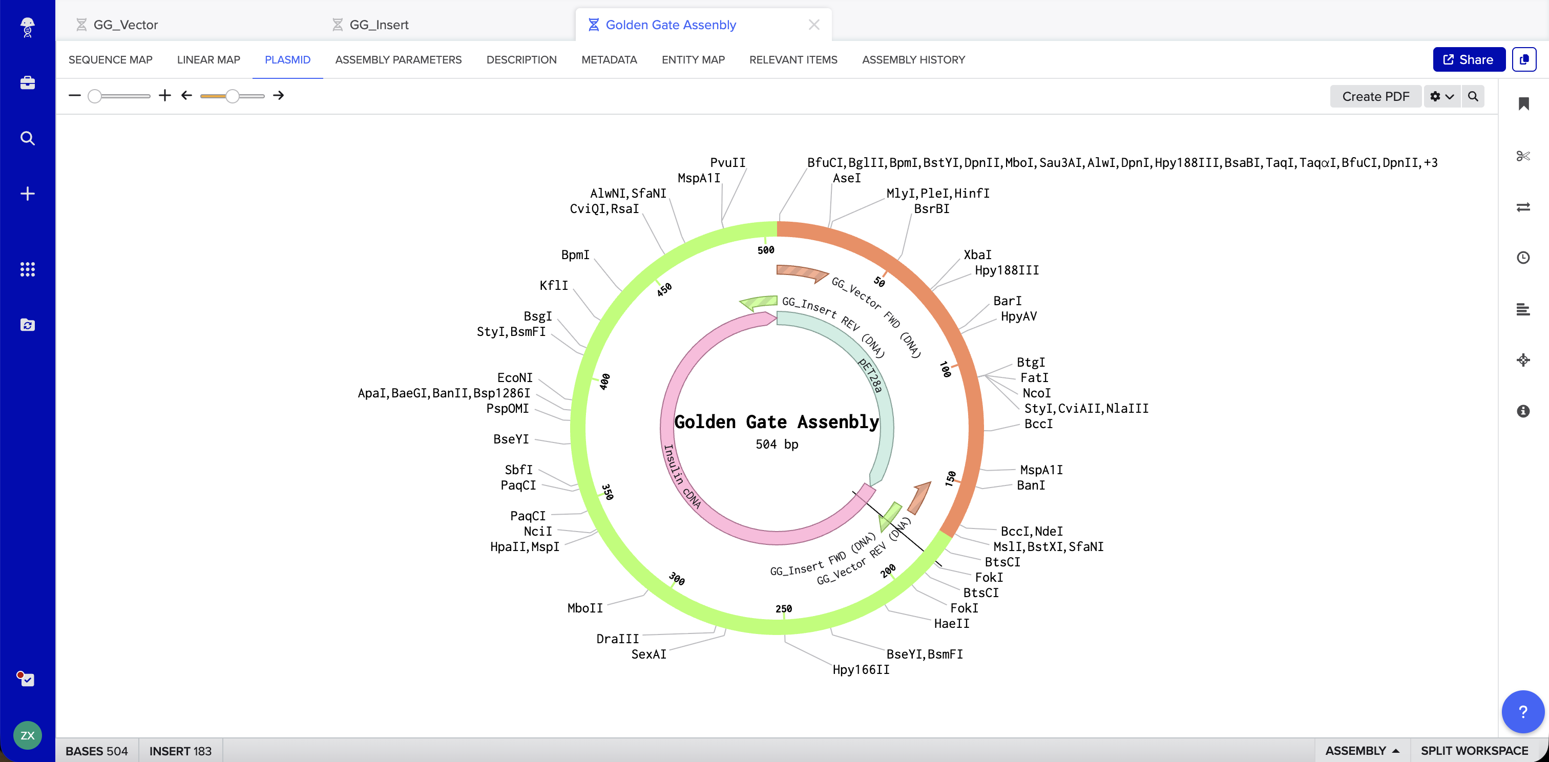
Golden Gate Assembly uses Type IIS restriction enzymes (such as BsaI) to generate unique 4-bp sticky ends on each DNA fragment. Unlike standard restriction enzymes, Type IIS enzymes cut outside their recognition sequence, so the recognition site is absent from the final product. Each junction is designed with a unique overhang, ensuring fragments can only assemble in one correct order. The reaction runs with both restriction enzyme and ligase in a single tube, cycling between digestion and ligation temperatures until the correct assembly accumulates.

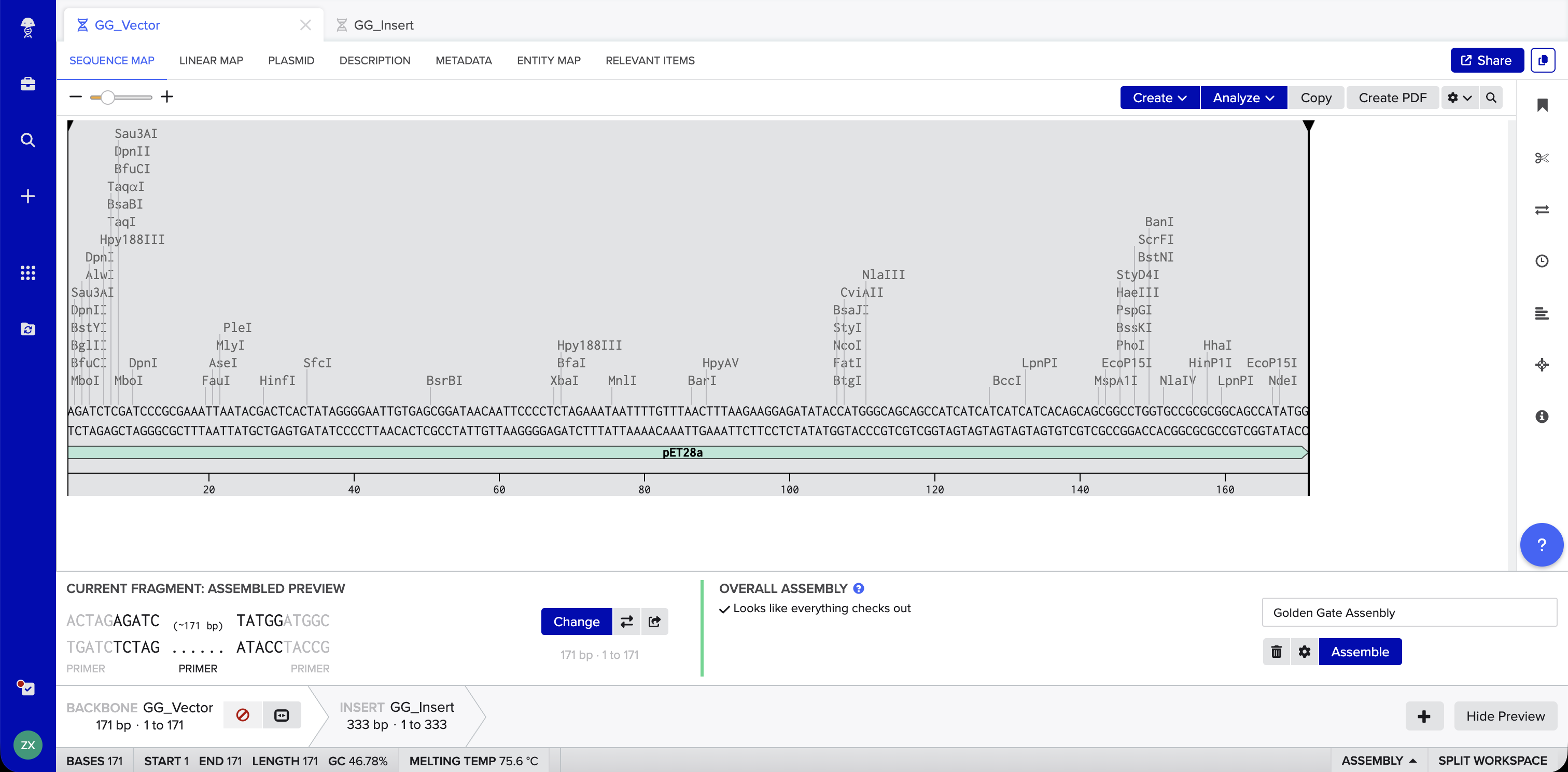
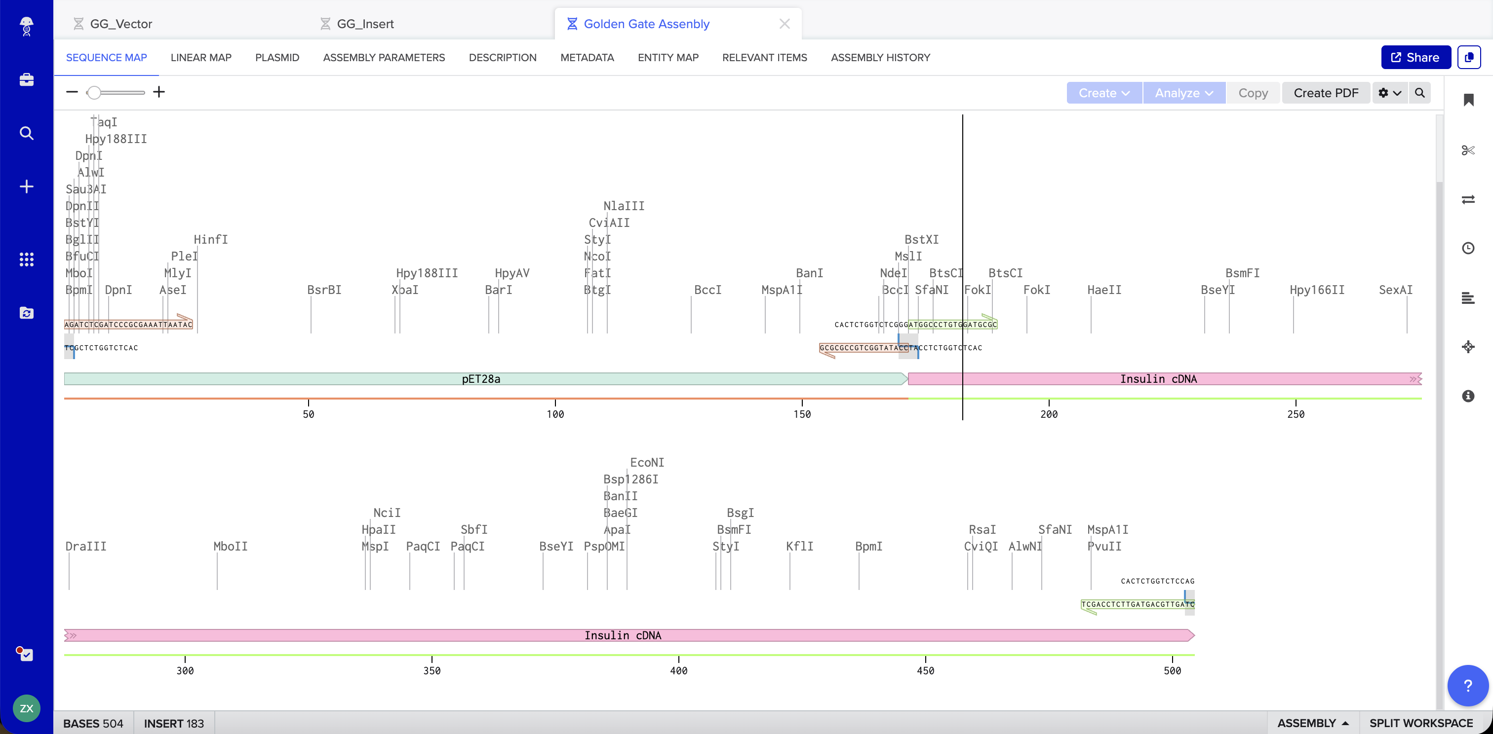
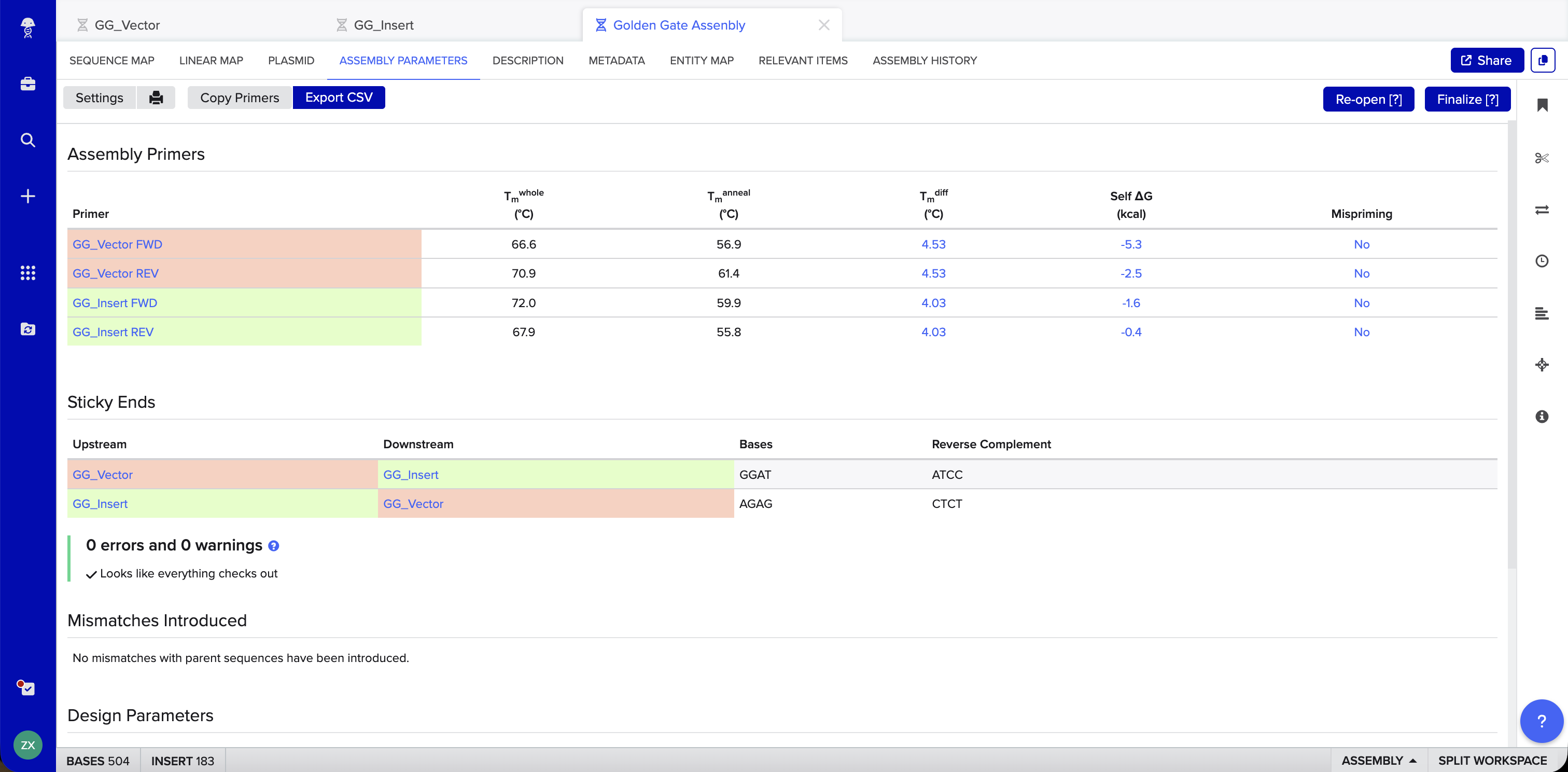
Benchling Simulation: The assembly was modeled in Benchling using a pET28a-derived vector (GG_Vector), a widely used bacterial expression vector, as the backbone and an insulin cDNA insert (GG_Insert). Benchling automatically designed four primers with BsaI recognition sites and generated sticky ends GGAT and AGAG at the two junctions. The plasmid map shows the vector and insert joined into a 504 bp circular construct with 0 errors and 0 warnings.
Asimov Kernel
Repository: Annie_Week 6 HW
Repressilator
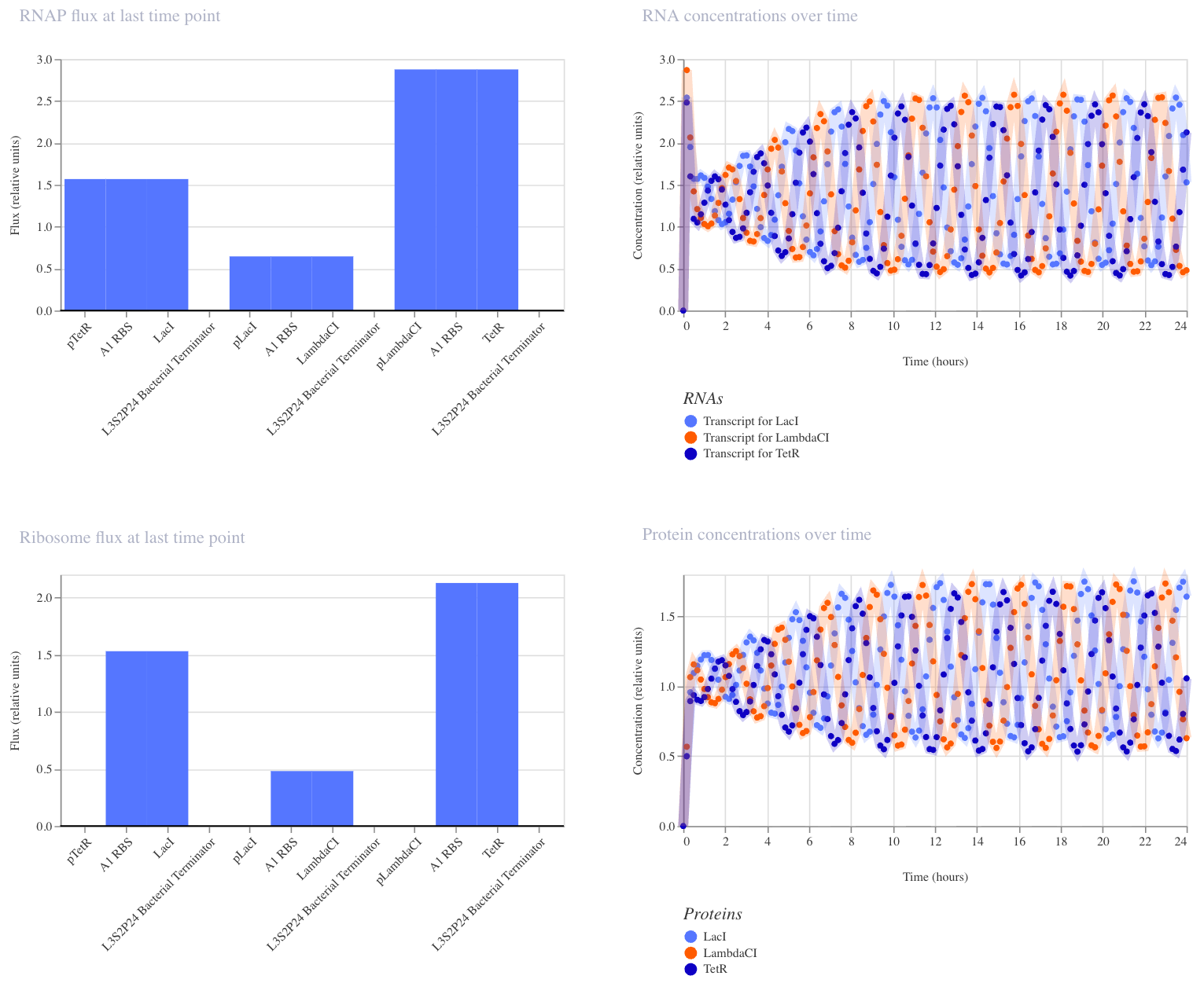
The repressilator is a synthetic genetic oscillator where three repressors are arranged in a negative feedback loop; each repressor inhibits the promoter driving the next:
pTetR → LacI → pLacI → LambdaCI → pLambdaCI → TetR → (back to pTetR)

No single protein can stay high for long, so the system continuously oscillates. I recreated the circuit in Kernel using parts from the Characterized Bacterial Parts repository and ran the simulator (E. coli, 24 hours, 10-minute timestep, transient transfection, no ligands). The simulator shows the expected oscillating expression of three repressor proteins (LacI, LambdaCI, TetR) cycling out of phase over 24 hours, confirming that each protein suppresses the next in the loop.
Custom Constructs
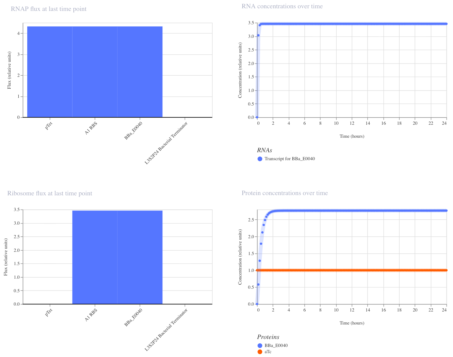
1. Single Reporter
This construct is a simple on/off switch: a single promoter (pTet) drives expression of GFP (BBa_E0040). pTet is normally repressed, but when aTc is added, it blocks that repression and GFP is produced. GFP should rise and hold steady after aTc addition.

I ran the simulator with aTc added at hour 0 (E. coli, 24 hours, 10-minute timestep, transient transfection). GFP rose quickly and plateaued at ~2.7 relative units, confirming that the circuit switches on as expected.
2. AND Gate
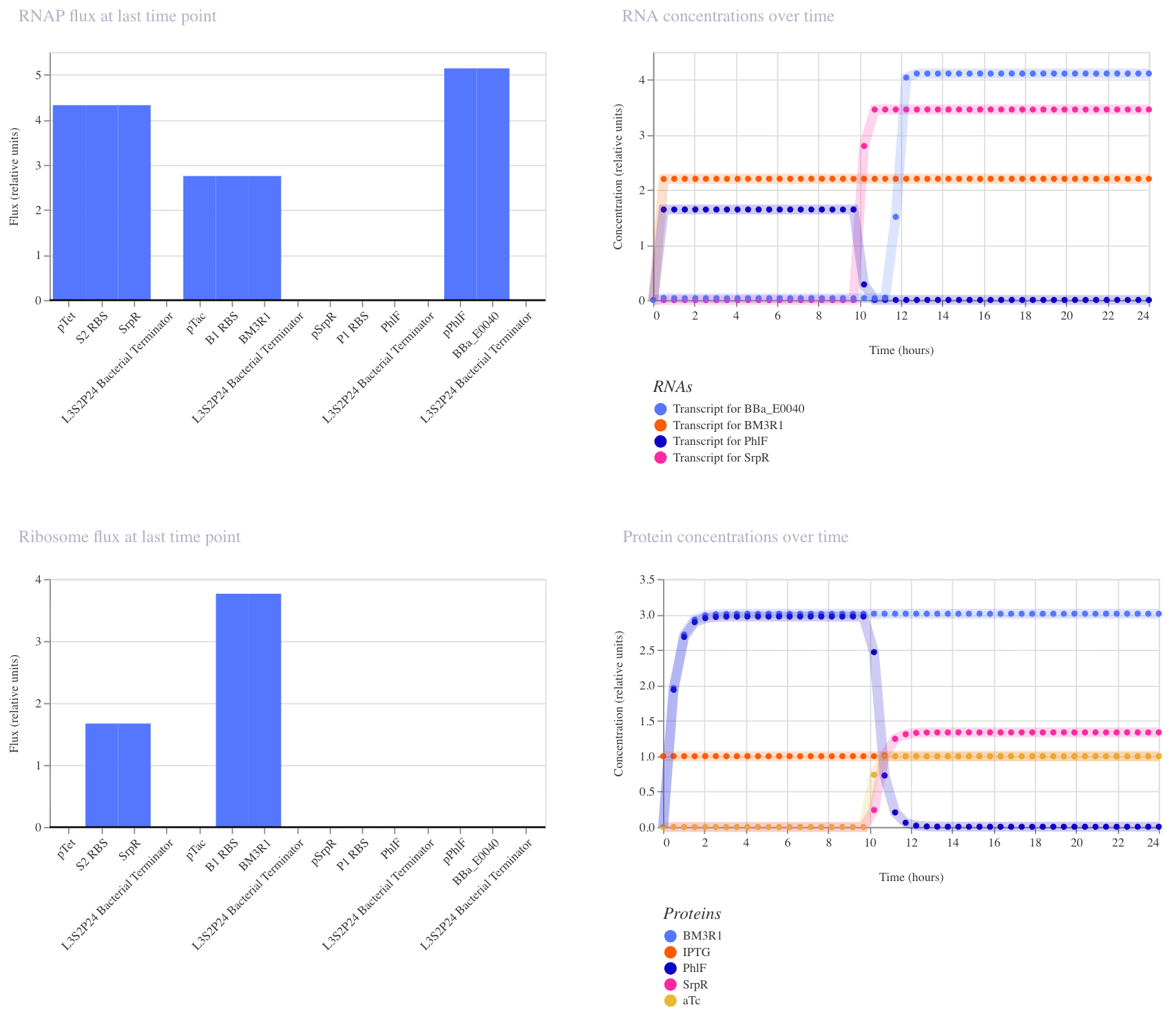
This construct implements two-input logic: GFP (BBa_E0040) is only produced when both aTc AND IPTG are present. The logic works through a double repression cascade: aTc induces SrpR and IPTG induces BM3R1, and both repressors are needed together to sufficiently suppress PhIF. Only when PhIF is low enough does pPhIF turn on and drive GFP expression. I expected GFP to remain off when only one input is present, and to switch on only when both inputs are active simultaneously.

I ran two simulations (E. coli, 24 hours, 30-minute timestep, transient transfection).
In the first run (aTc at hour 0, IPTG at hour 10), the results didn’t fully match expectations: GFP appeared elevated before both inputs were present, suggesting leakiness where one repressor alone was partially sufficient to suppress PhIF. This likely reflects imperfect repression strength in the cascade, which is a known limitation of cascaded repressor designs.
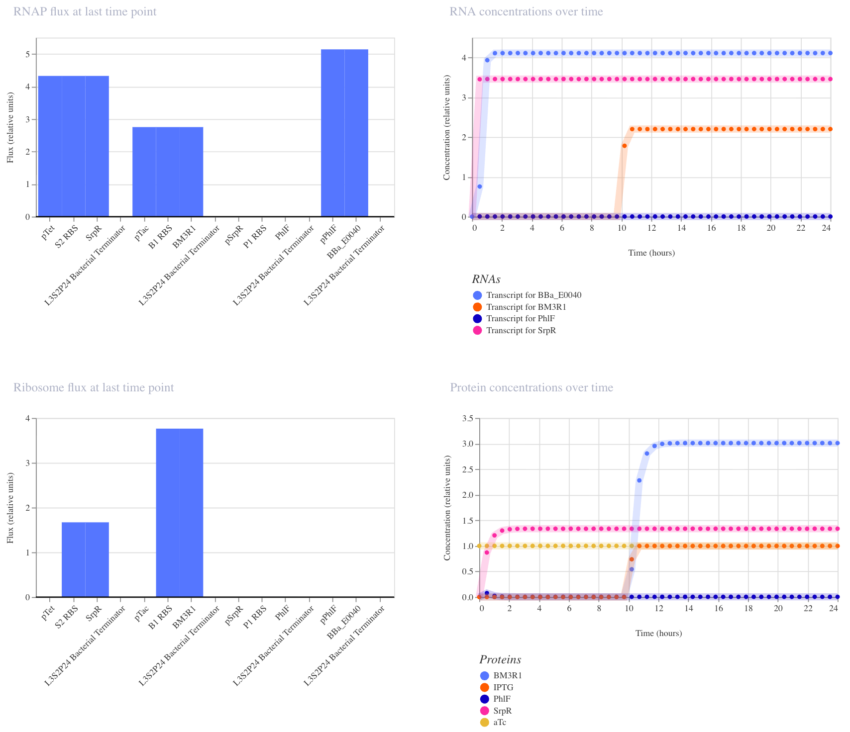
In the second run (IPTG at hour 0, aTc at hour 10), the expected AND gate behavior was clearly visible: GFP remained off until aTc arrived at hour 10, then switched on sharply. This confirms that both inputs are required for full GFP activation, and that the order of input delivery affects how cleanly the logic is observed.
3. NAND Gate
This construct implements NAND logic: GFP (BBa_E0040) is ON by default and only turns off when both aTc AND IPTG are present. aTc induces SrpR via pTet, and IPTG induces PhIF via pTac. Only when both repressors are active simultaneously is pSrpR sufficiently repressed to turn off GFP. I expected GFP to be on in all conditions except when both inputs are present together.

I ran three simulations to test this (E. coli, 24 hours, 30-minute timestep, transient transfection).
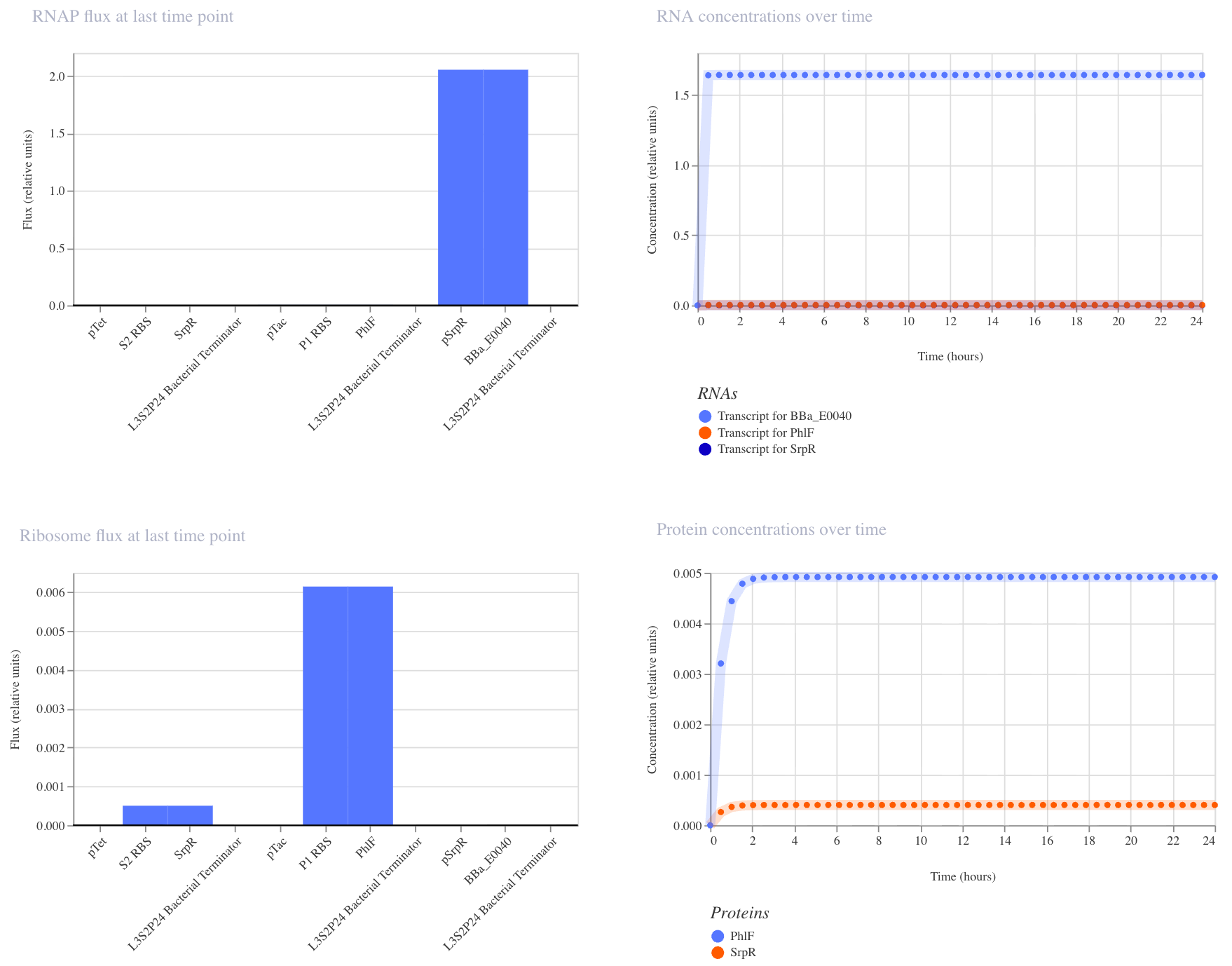
With no inputs, GFP RNA was high (~1.7), confirming it is on by default.
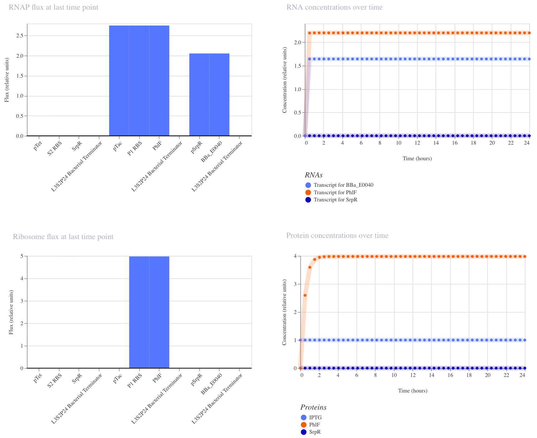
With IPTG alone, GFP RNA remained high, confirming that a single input is insufficient to turn it off.
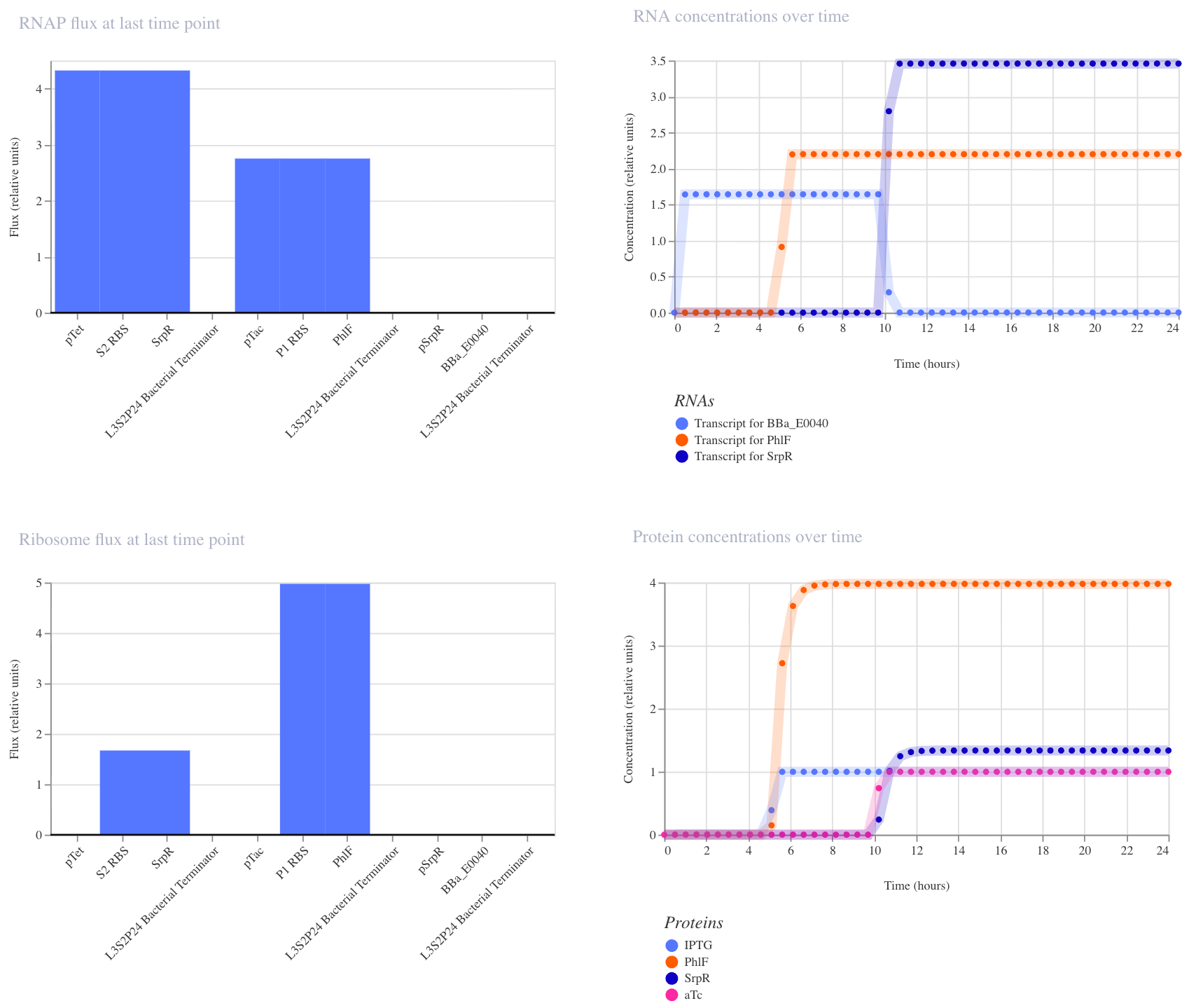
In the third run (IPTG at hour 5, aTc at hour 10), GFP RNA stayed high until aTc arrived at hour 10, at which point it dropped to near zero, confirming that both inputs together are required to turn GFP off. This matches the expected NAND behavior.