Hi! It is my pleasure to introduce myself to everyone. I am a recent graduate in architecture, I live in Medellín Colombia and I love having the opportunity of learning about a future where the opportunity of access to laboratories is global and not just for academic strictly form, I am here because I am interesting in how we could build a future that function from the mixture of the most advances technologies, the conscient design and nature as the most complete aspect to build a sustainable future that could function for everyone. I have some experience in investigation where I worked with subjects as “urban heat islands” or “constructed wetlands”, from this moment I started to be interested in how we could find a new way of constructed or cities of materials that are more resilient and adaptable to any situation, while simultaneously contributing to the improvement of our environment.
Contact info
Homework, Labs, and Projects
See the nav bar on the left to look through my work for How To
Biomanufacture Almost Anything (Fall 2026)!
Subsections of KAROL CUELLAR — HTBAA Fall 2026
Week 1 HW: Final Project Ideas
What you would like to biomanufacture and why?
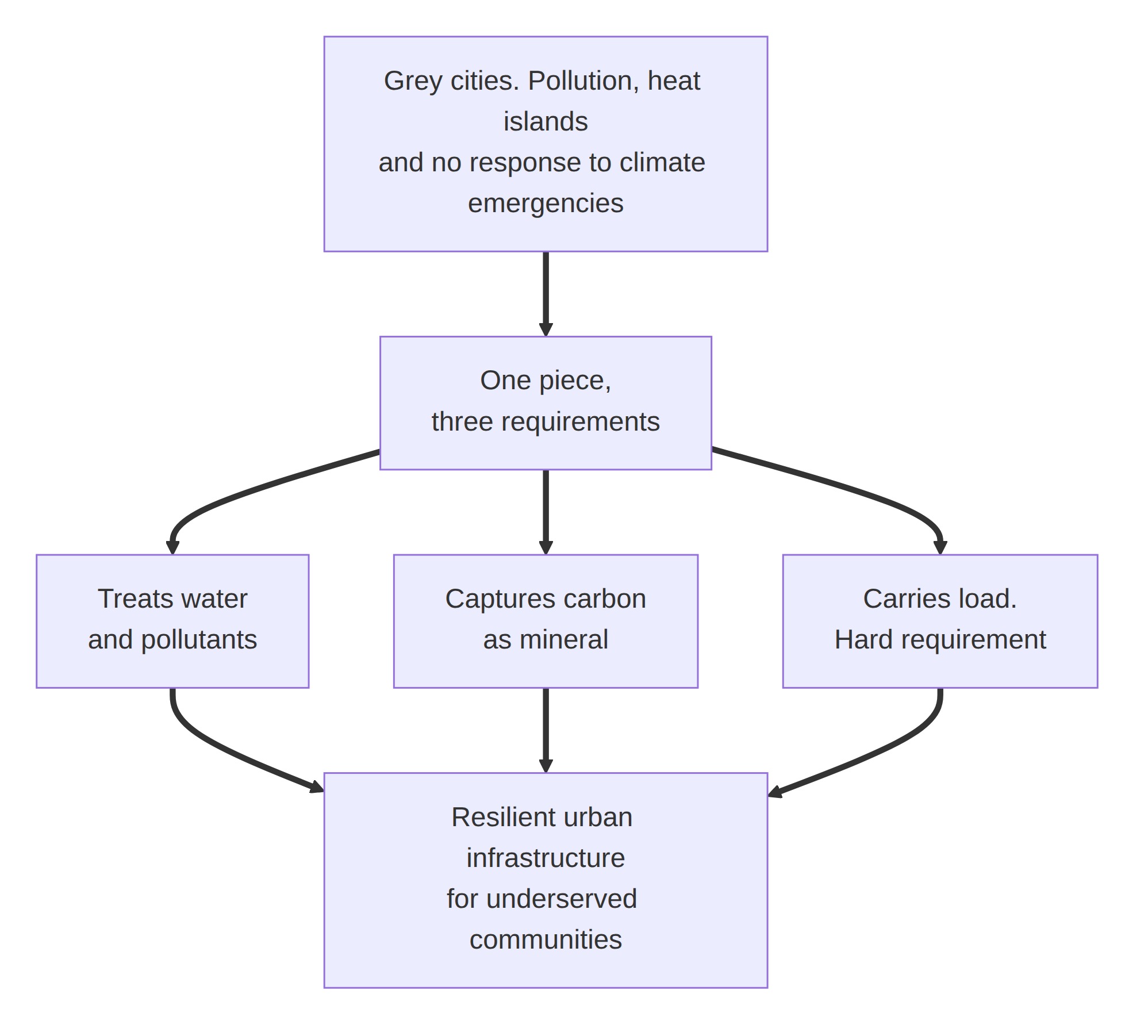
I find the problem of our buildings pressing. Rather than contributing to the health and improvement of our urban ecosystems, their production generates high levels of pollutants and contributes to a vast sprawl of grey cities that cannot respond to climate emergencies and that create heat islands. With everything that has been developed recently, it is time to build not only so as not to pollute, but to gradually return the quality of our urban environments to ecosystems where nature and development can coexist healthily.
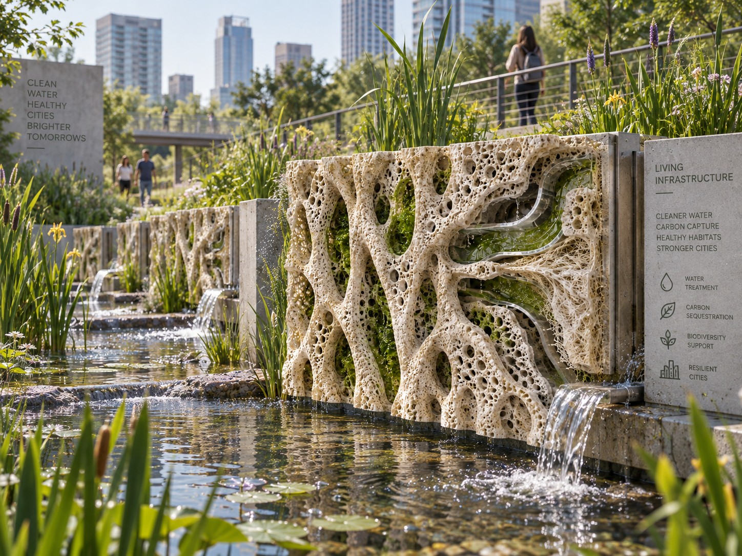
Out of that problem, my interest is to create a prototype of a resilient infrastructure for the improvement of our cities: a piece that treats pollutants and captures carbon, that handles water in urban settings, and that can serve the communities with the least access to sanitation — where a construction element that also cleans is worth more than one that only encloses. A resistant but adaptable infrastructure that fuses biotechnological elements by adapting the particular functions of photosynthesis, bioremediation and metabolism, through microorganisms living together inside a ribbed coral structure that grows and anchors itself to the site, offering safe construction alternatives that give something back to our urban ecosystems and transform them.
What living system would you use?
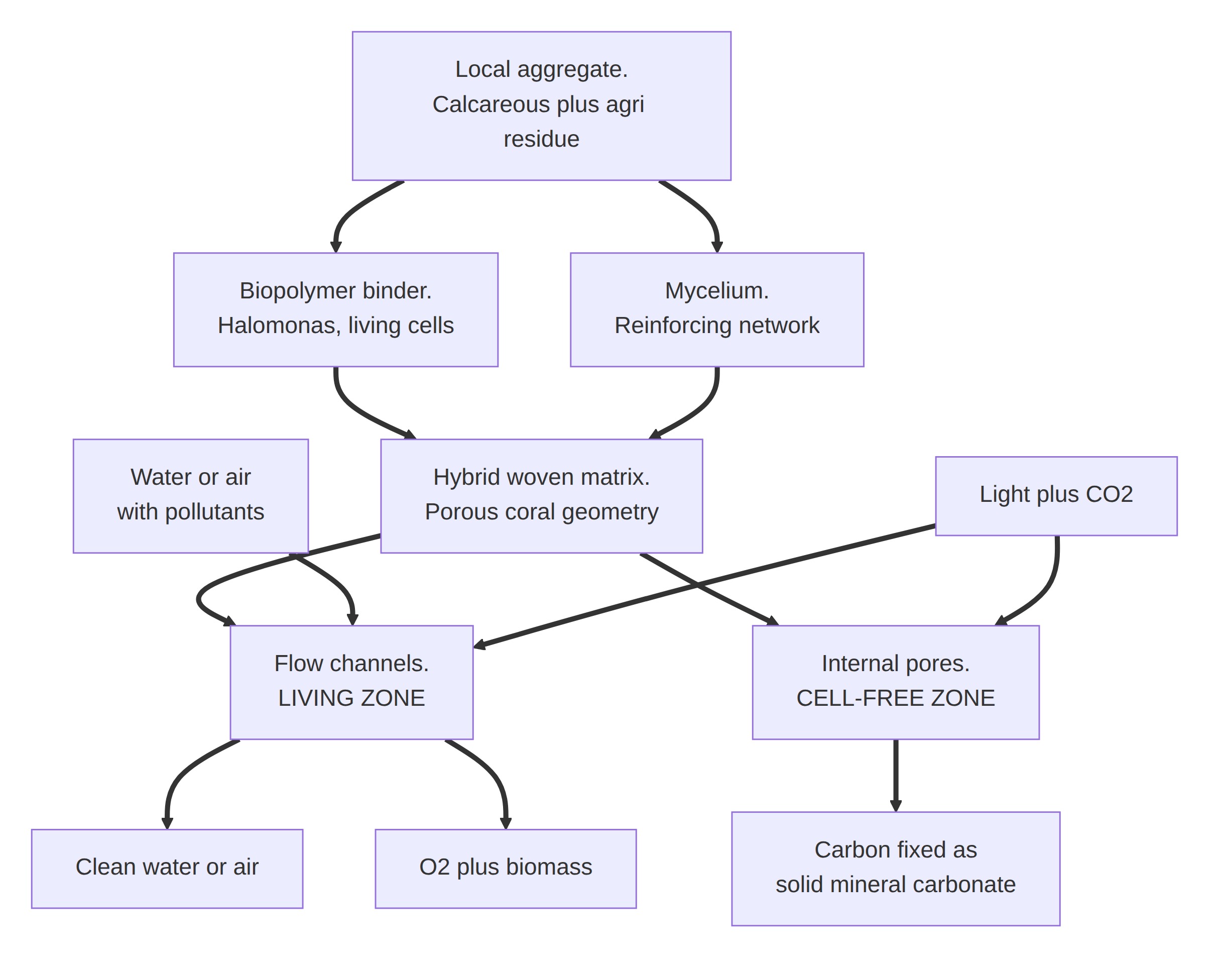
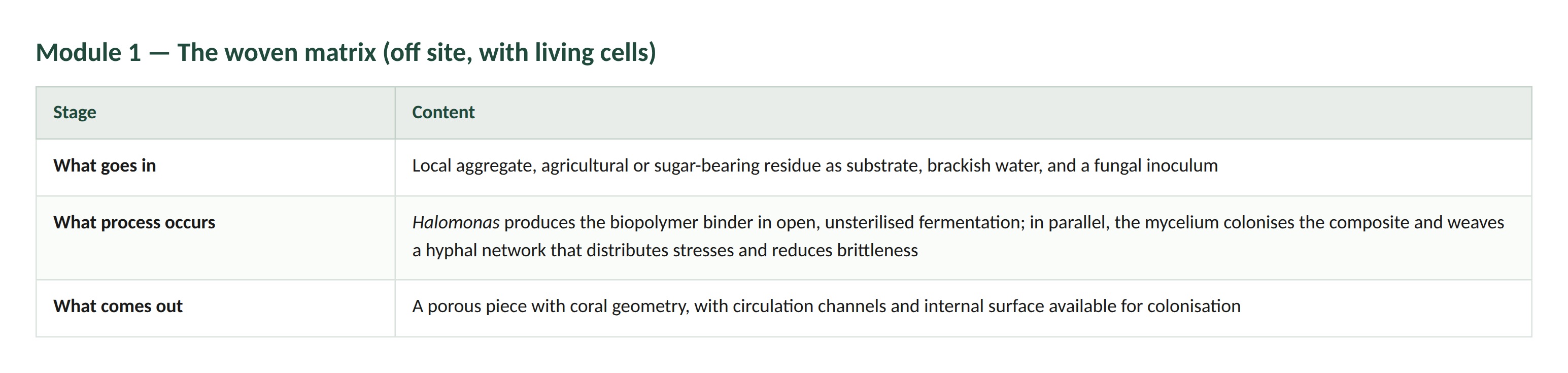
I propose a system with two parts, following the logic of cultured-meat biomanufacturing: an infrastructure that hosts, and a biological phase that works. The infrastructure is a hybrid matrix of local aggregate bound with a biopolymer binder and woven internally by a mycelium network, with a porous coral geometry whose channels act as a circulation system for water or air depending on where the piece is installed. As with the cultured-meat scaffold, it is a design object with simultaneous requirements: porosity so that the biological phase can live, rigidity so that the piece can resist, and a final property for the user which here is not flavour but the capacity to clean and to capture carbon.
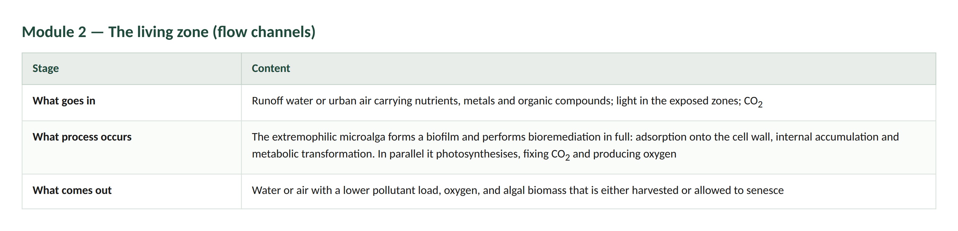
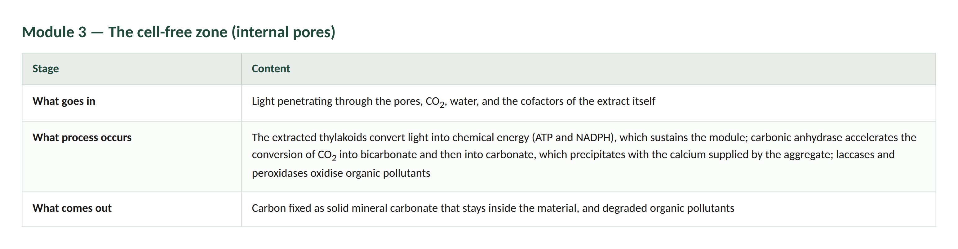
The biological phase consists of extremophilic microalgae used in two states depending on the zone. In the flow channels, where there is water and light, the whole living organism is used: there, bioremediation happens in full — adsorption onto the cell wall, internal accumulation and metabolic transformation — and the biofilm replenishes itself. Inside the material, where nothing living can be sustained, the alga enters as a cell-free extract: the cells are lysed and the thylakoids, carbonic anhydrase, laccases and peroxidases are immobilised on the pores. Light, CO₂, water and contaminated air or water go in; conversion of light into chemical energy, carbon fixation, catalysed hydration of CO₂ to carbonate and enzymatic oxidation of organic pollutants take place; oxygen, carbon fixed within the material, and air or water with a lower pollutant load come out.
To arrive at the right alga I follow five steps: select a robust microalga for its tolerance to heat, pH or salinity; study its actual capacity to remove pollutants; extract and stabilise its biomass in vitro; integrate the extracted component into the matrix; and test, beginning with the infrastructure alone before measuring the assembly. The extraction step is carried out hot if the microalga is thermophilic, because the enzymes of interest then survive while the rest denatures: this purifies the extract without chromatography and avoids having to work in a sterile environment, which is the cost that would make a cell-free system unviable.
The carbon-fixation module builds on the CETCH cycle, a synthetic pathway assembled in vitro with enzymes from nine organisms across the three domains of life, which in 2020 was combined with photosynthetic membranes inside ninety-micron droplets to achieve light-driven CO₂ fixation. That work is my precedent that a light-powered, cell-free carbon-fixation module is feasible. My variant proposes that the membranes come from the extremophilic microalga rather than from a plant, so that the resulting artificial chloroplast tolerates hot processing. The scale matches: one pore of my matrix is the size of one of those droplets.
Where the captured carbon ends up. This is a decision, not an open option. The CETCH cycle yields glyoxylate, an organic molecule that leaves the material dissolved; carbonic anhydrase instead takes CO₂ to bicarbonate and then to solid carbonate, which stays inside the piece. I choose the second route: the captured carbon is mineralised in place. The thylakoids supply energy and drive the local conditions; carbonic anhydrase does the conversion; the carbon remains as mineral.
Mineral carbonate needs a cation to precipitate, so the aggregate is not neutral in this choice: a calcareous local aggregate — limestone fines, marble dust, crushed construction waste — supplies the calcium and closes the loop, because the captured CO₂ then precipitates as additional mineral binder within the pore. Carbon capture and mechanical consolidation become the same event rather than two competing functions, which matters given that strength is a hard requirement of this system.
I assume that the photosynthetic apparatus retains activity when immobilised on the pore surface, that the pH of the matrix is compatible with the chosen enzymes, and that the film can be recharged. The most important unverified assumption is the working life of the catalyst: without a cell there is no repair of the photosystem and no automatic correction of metabolic errors, and that is the variable that would decide whether the system works.
The mycelium here is what the coral project calls biological glue: it reinforces the matrix from within and improves cohesion between particles. It is what turns an aggregate-and-binder composite into a woven structure
This zone justifies keeping the whole organism: the three mechanisms of bioremediation — bioadsorption, bioaccumulation and biotransformation — only work in full with a living cell. And it replenishes itself.
How would you use automation?
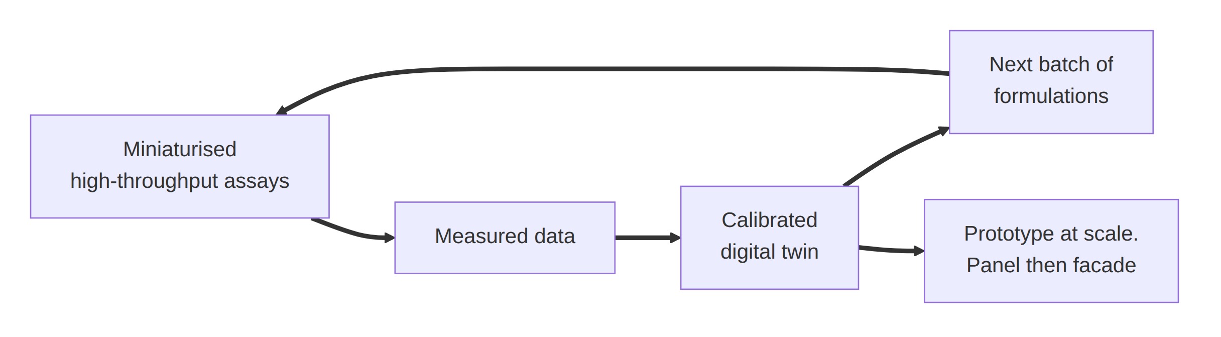
I would combine two technologies that only make sense together: a digital twin of the piece, and an automated workflow of miniaturised high-throughput assays. What I automate is the loop between the two, that is, the design–build–test–learn cycle.
The step of the workflow that I automate is the screening of formulations and their measurement: preparation of mixtures with a liquid-handling robot, inoculation and parallel culture on test specimens with controlled light and flow, and automatic sampling and reading of the effluent, of biomass via chlorophyll, and of enzymatic activity. I choose that step because that is where the design space lies: my factorial design alone — geometry, biological combination, inoculation strategy and nutritional condition — yields 36 treatments and 324 experimental units in a single round, and that is with the combinations already filtered. Petzold and Mukhopadhyay put the general problem at roughly 10²⁴ possible variants for the engineering of a single metabolic pathway. That space cannot be covered by hand.
The order matters, and it is a loop rather than a queue. A digital twin without measured data is not a twin but a rendering: simulating a material that does not yet exist requires measured parameters — composite strength, algal removal rate, actual permeability of the geometry — and those come only from physical experiments.
Miniaturised high-throughput assays → Measured data → Calibrated digital twin → Proposes the next batch of formulations → (back to the assays)
Calibrated digital twin → Prototype at scale: panel or façade
What the digital twin is, concretely
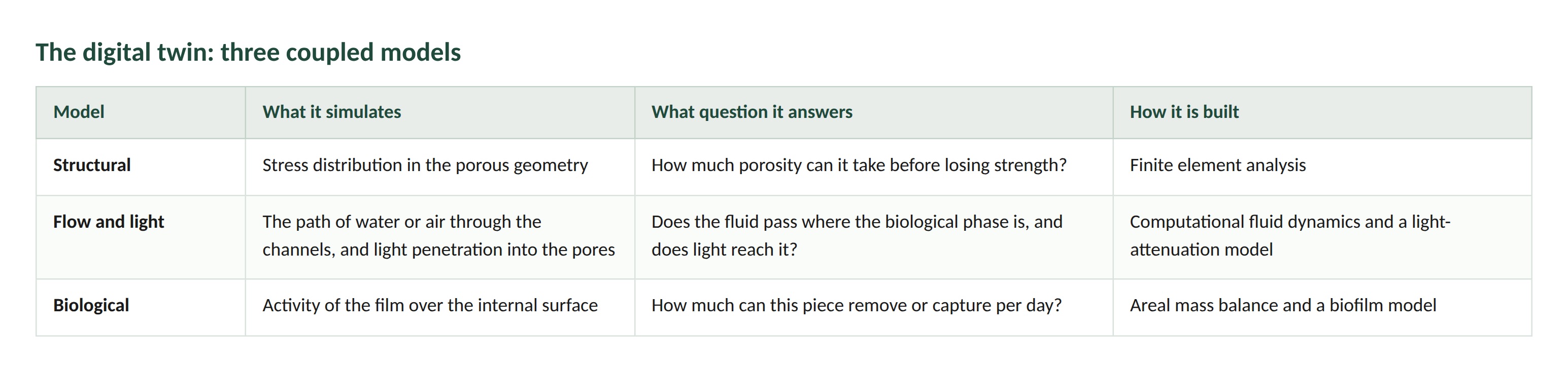
It is not a program you buy: it is three coupled models that share the same geometry.
The biological model also incorporates a physical limit: the substrate enters the film by diffusion and is consumed as it penetrates, so beyond a certain thickness the film is inert. The design consequence is that the capacity of the system is governed by the internal surface, not by the volume of biomass — and internal surface is precisely the variable that geometry controls. Simulating before fabricating makes it possible to discard unviable geometries without building them, and to scale in stages — test specimen, 30 × 30 cm panel, façade module — checking at each jump whether the areal rate measured at the small scale holds at the large one.
How much would you need to make, and how long would it take?
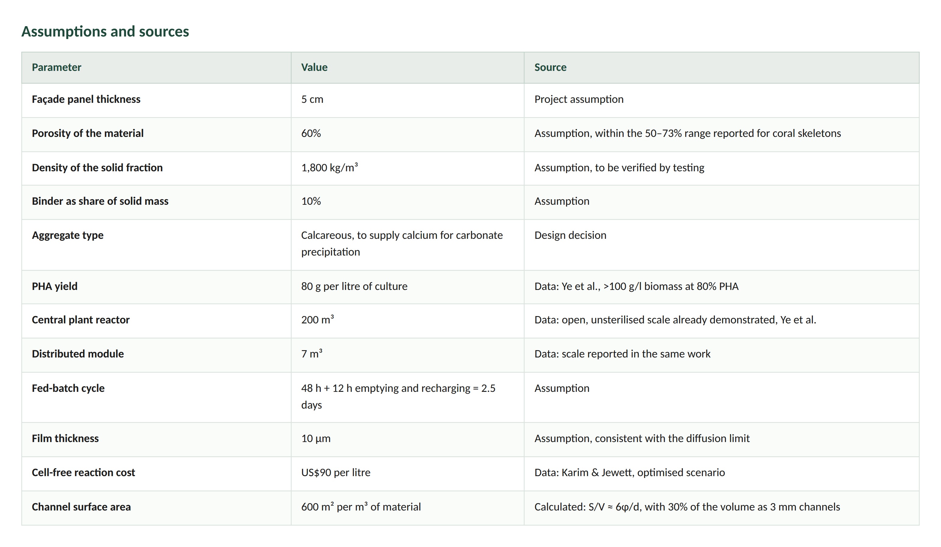
A note on cost first. The figure of US$90 per litre from Karim and Jewett is the cost of the cell-free reaction, not of the material. Applied to the mass of the wall, a façade would cost millions. Applied only to the volume of the film — a layer of microns over the channel walls — the figure becomes manageable. The whole calculation depends on keeping that distinction.
(a) How much — Scale 1: a 500 m² façade
I define two scales. The unit is a 500 m² façade with 5 cm panels and 60% porosity: 25 m³ gross, 10 m³ of solid, 18 tonnes of material and, with the binder at 10% of the mass, 1.8 tonnes of biopolymer. At the yield reported for Halomonas bluephagenesis — more than 100 g/l of biomass at 80% PHA, that is 80 g per litre of culture — that comes to 22,500 litres of culture. The cell-free film covers only the walls of the circulation channels, some 15,000 m² of internal surface, and at 10 microns thick it requires 150 litres of extract, which at the optimised cost of 90 dollars per litre comes to 13,500 dollars, roughly 27 dollars per square metre of façade.
Cement displaced. An equivalent panel in concrete would weigh some 60 tonnes and contain around 7 tonnes of cement. At an intensity of 0.6 to 0.9 tonnes of CO₂ per tonne of cement, the façade would avoid on the order of 4 to 6 tonnes of CO₂.
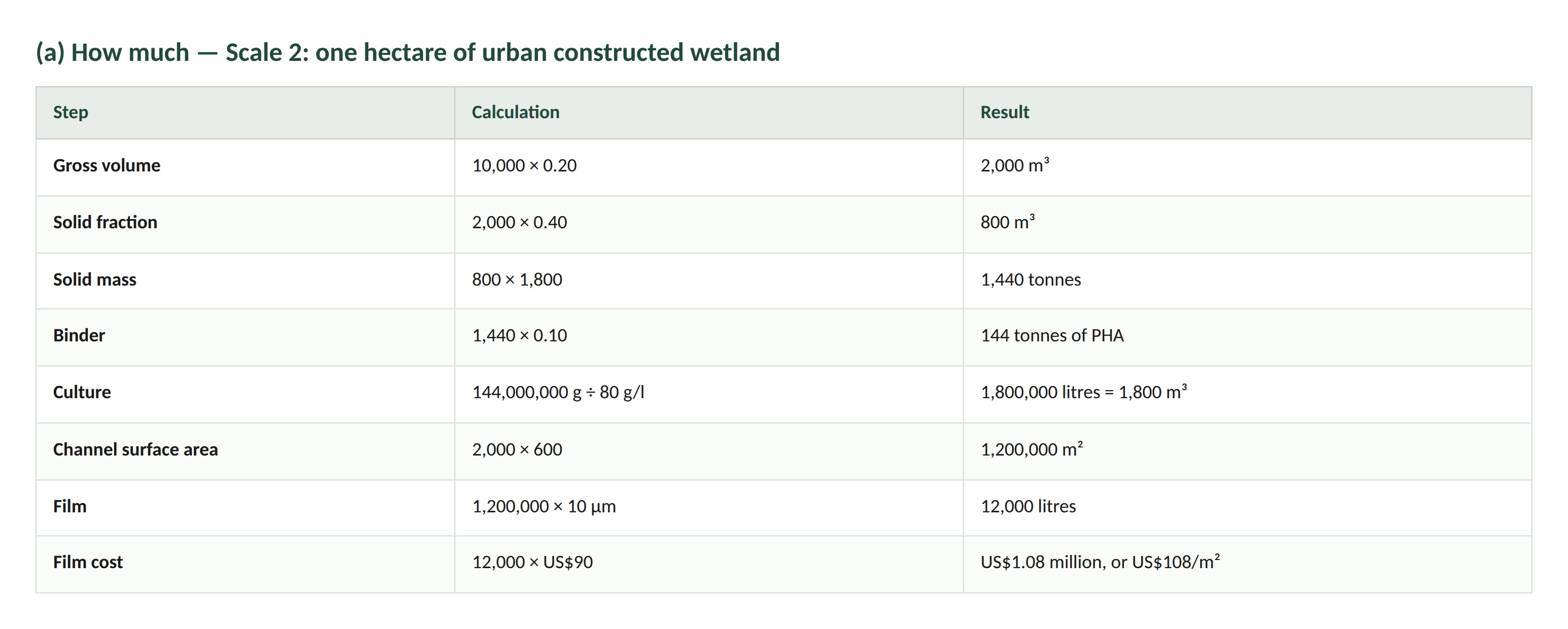
(a) How much — Scale 2: one hectare of urban constructed wetland
The same logic applied to 10,000 m² with an average bed thickness of 20 cm:
(b) How long
With a fed-batch cycle of 2.5 days, a distributed 7 m³ module produces 560 kg per batch and a 200 m³ central plant produces 16 tonnes. The façade is resolved in four module batches, or in less than one central batch; the hectare requires nine central batches, roughly 22 days. A single central plant of the size already demonstrated in open fermentation produces, per year, the binder for about a thousand façades or thirteen hectares of wetland.
Prototyping and production are not the same technology. For prototyping I would use 7 m³ modules next to each residue source, which allow different local substrates to be tested, together with liquid-handling robotics and miniaturised assays. For production at scale I would use a 200 m³ central plant in open continuous fermentation, and a 20 m³ cell-free reactor with thermophilic enzymes purified by heat treatment.
What the calculation reveals
The calculation exposes a design constraint I had not anticipated. The specific surface of a porous solid is approximately 6φ/d, so 100-micron micropores offer some 36,000 m² per m³ against the 600 m² per m³ of millimetric channels. Coating that entire surface with extract would cost around 810,000 dollars per façade instead of 13,500. The conclusion is that the cell-free film must be restricted to the channel walls, which coincides with the diffusion limit: neither light nor flow reaches the deep micropores.
Finally, the areal rate of capture or removal per square metre per day is not available in the literature I consulted, and is precisely what the automated screening measures. Inverting the question: for the façade to capture one tonne of CO₂ per year, each square metre of channel must fix about 0.18 grams per day. That is the threshold the assays would have to exceed.
The estimate leaves out downstream processing, which according to Asin-Garcia et al. accounts for between 15% and 90% of total production cost; the substrate balance, that is, how many tonnes of local residue are needed to feed the culture; the development time, which for the artemisinin-producing yeast ran to some 150 person-years; and ageing, since the calculation covers first installation and not maintenance.
What don’t you know yet?
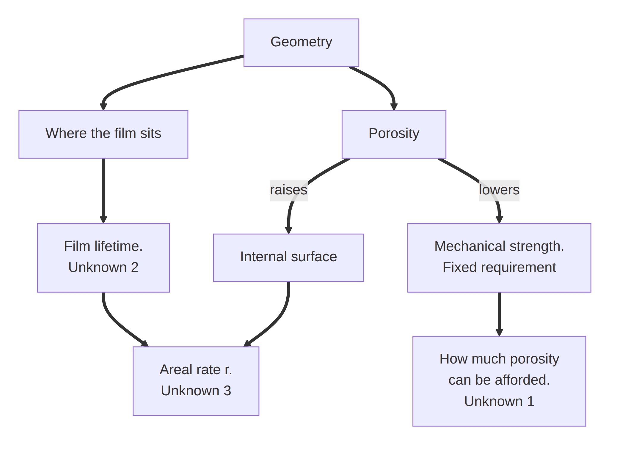
The three largest unknowns in my system are, in order of consequence: whether the geometry holds, how long the film lasts, and how much it captures per square metre.
The first is a design conflict, not a detail: remediation capacity depends on internal surface, which grows with porosity, while mechanical strength falls with it. The readings on coral skeletons describe that inverse relationship, but nobody has measured the curve for a composite of local aggregate with a biopolymer binder and mycelium reinforcement, because it does not exist. I would need to establish the compressive and flexural strength curve between 40% and 70% porosity, with and without mycelium, dry and wet, and after wetting and drying cycles, and compare it against the code requirements for the intended use. Strength here is a constraint, not an outcome: the piece has to be structural. So the variable that yields is porosity. The real question is how much porosity the material can afford while still meeting the requirement, and the risk is that at the minimum viable porosity the internal surface is too small for the biological phase to do anything worth doing. Two things work in my favour: the mycelium network, which raises cohesion without adding mass, and the mineralisation of captured CO₂ as carbonate, which consolidates the piece over time instead of competing with its strength.
The second follows directly from having chosen a cell-free system: without a cell there is no self-repair, and photosystem II photodamages without the replacement cycle it has inside the organism. Karim and Jewett list catalyst stability as an explicit limitation. I would need to measure residual enzymatic activity per unit of surface against time, under realistic humidity and radiation cycles; the only reference available — 87.9% of activity retained after four cycles for carbonic anhydrase — is from the laboratory. If activity falls below half within a year, the film changes from a component into a consumable, and the economics change with it.
The third is the only figure I could not take from the literature: the areal rate of capture and removal, because it depends on the specific combination of organism, light and flow. It is exactly what the automated screening described in answer 3 produces. The threshold is calculated: for a 500 m² façade to capture one tonne of CO₂ per year, each square metre of channel must fix 0.18 grams per day. If it falls short, the project retains the argument of displaced cement and that of water remediation, but loses the carbon-capture argument.
The three are coupled. Porosity raises biological capacity and lowers strength; the life of the film depends on where it sits; and the areal rate depends on whether flow and light reach it. There is a three-variable optimum that cannot be found by testing one at a time, and finding it is exactly what coupling the digital twin with the automated screening is for.
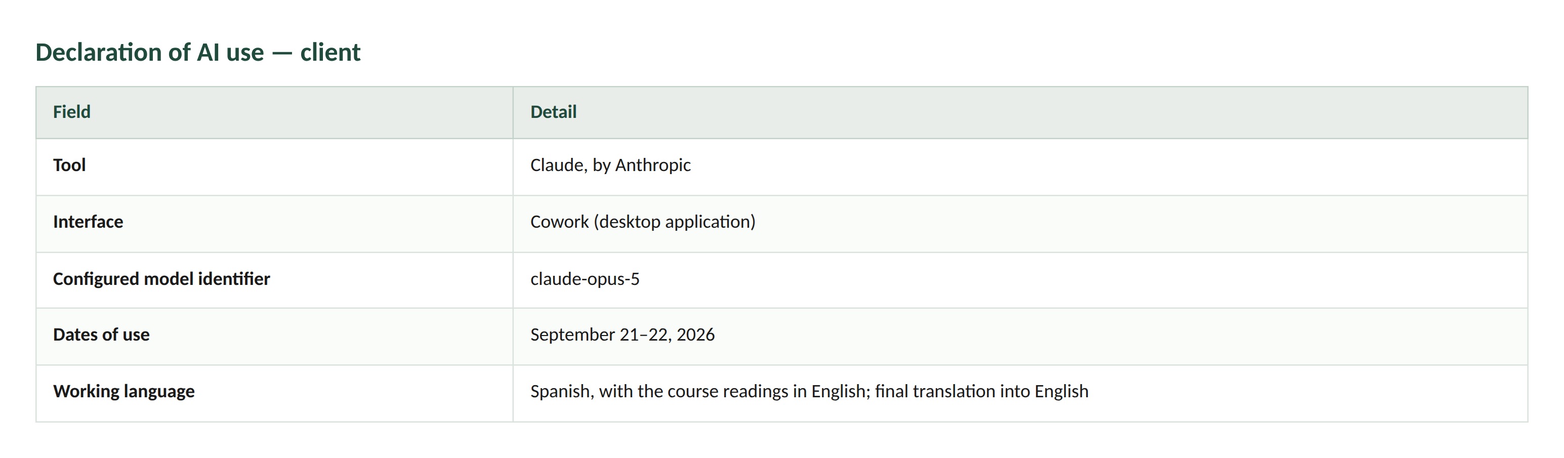
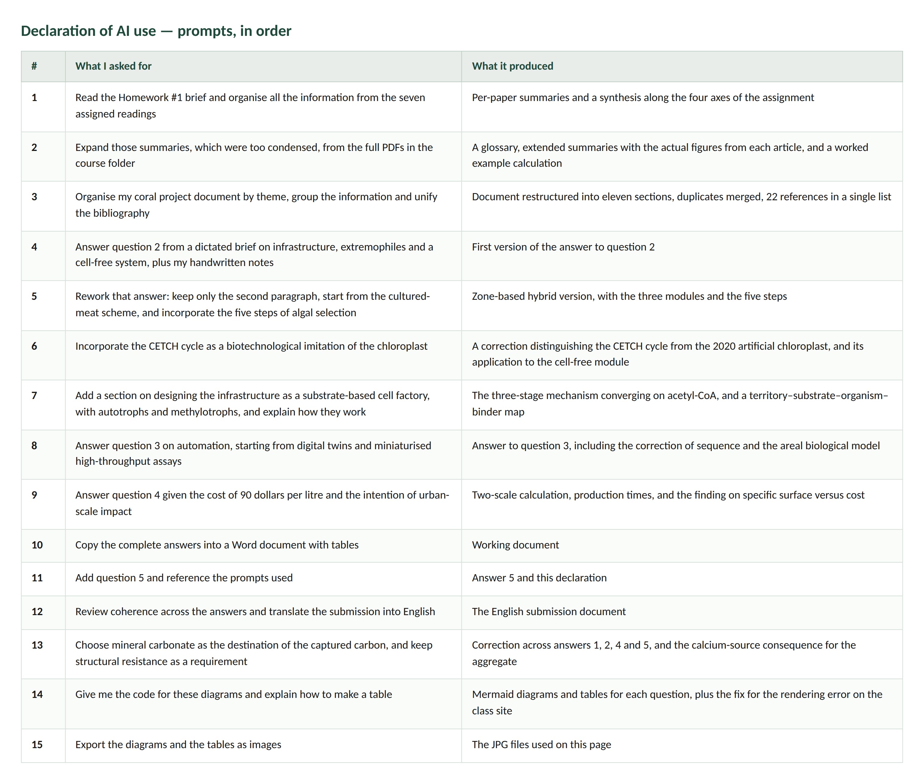
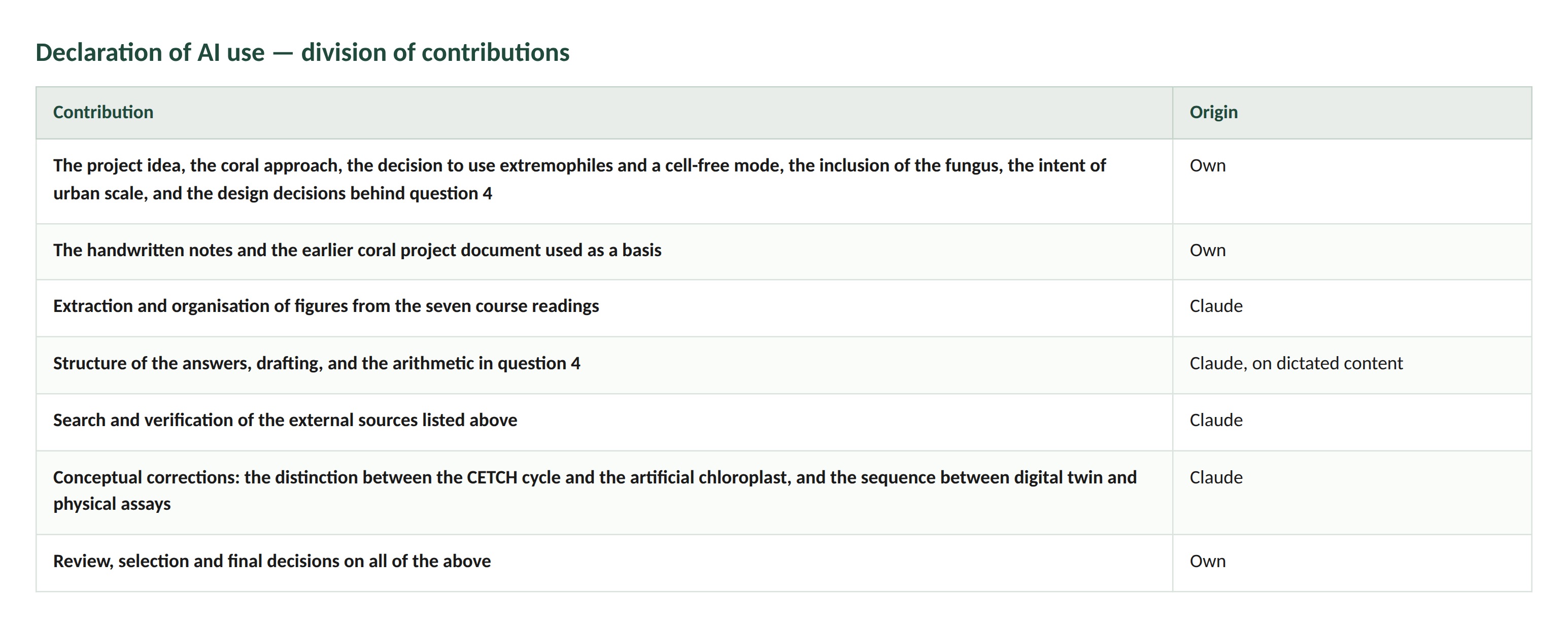
Declaration of AI use
Week 2 HW: DNA Design
“Homework 2 — DNA Design” subtitle: “Bio Storage Water Management: designing the CsgA–SmtA fusion” author: “Karol Eliana Cuellar Narváez” date: 2026-10-07
Homework 2 — DNA Design
Project: Bio Storage Water Management — a flexible, microperforated honeycomb panel that captures, stores and cleans urban rainwater.
In Homework 1 I proposed the panel. Here I design the DNA that makes the material it is built from.
Figure 1. Design of the CsgA–SmtA fusion and its path from coding sequence to urban deployment, across five scales. (01) The 633 bp CDS encodes mature CsgA (UniProt P28307, residues 21–151) joined by a (GGGGS)₃ linker to the cyanobacterial metallothionein SmtA (UniProt P30331), with a C-terminal His₆ tag; 210 aa, ~20.7 kDa. (02) Expression in the reducing cytoplasm of E. coli BL21(DE3), followed by denaturing lysis and Ni-NTA purification; no living organism continues past this step. (03) In vitro self-assembly into amyloid nanofibres displaying SmtA, entangling into a porous network that retains water and chelates Zn²⁺, Cd²⁺ and Cu²⁺. (04) The network packs the cells of a flexible microperforated honeycomb panel whose depth varies with stored volume. (05) Captured rainwater is routed either to soil root networks or to artificial urban wetlands. Fusion strategy after Nguyen et al., Nat. Commun. 5:4945 (2014).
Part 0 — Set up in Kernel
Repository: Karol Eliana Cuellar Narvaez
Folder: Cuellar Karol-Bio water storage and management
Construct: pET28a_CsgA-SmtA
Part 1 — Define the expression target
What molecule am I expressing?
A single designed fusion protein, CsgA–SmtA, which performs two of the three functions of my panel in one polypeptide.
CsgA is the major curli subunit of Escherichia coli: it self-assembles into extracellular amyloid nanofibres, forming a dense, hydrophilic, mechanically robust porous network. In my design this network is the storage matrix inside each honeycomb cell of the panel — the water-retaining phase, not an inert support.
SmtA is a cyanobacterial metallothionein that binds divalent heavy metals (Zn²⁺, Cd²⁺, Cu²⁺) through cysteine thiolates. Fused to the C-terminus of CsgA, it is displayed along the surface of every fibre, so the same material that holds the water also strips metals from it.
My HW1 product is a material, so this is the protein that produces it: the fibres are the material.
What is the sequence?
Where does the product need to go?
The cytoplasm, with no signal peptide and no secretion. This is the design decision that most distinguishes my construct from the published BIND system, which secretes CsgA fusions through the CsgG pore onto the cell surface. I chose cytoplasmic accumulation for three reasons.
Redox. SmtA coordinates metals through reduced cysteine thiolates, and the E. coli cytoplasm is a reducing environment that preserves them. Export to the oxidising periplasm risks non-native disulfide formation across the nine cysteines and loss of the metal-binding sites.
Size. The CsgG secretion channel constrains what can pass; removing secretion removes that constraint from any future variant.
Architecture. By purifying unassembled CsgA–SmtA and triggering assembly in vitro, I control where the fibre network forms — it nucleates on the microperforated geometry of the panel cell, in the shape the architecture requires, rather than on the surface of bacteria I would then have to remove.
A known trade-off follows: cytoplasmic CsgA is expected to accumulate in inclusion bodies and will require denaturing purification followed by controlled refolding and assembly. I treat that as an accepted cost, and return to it in Part 6.
Part 2 — Design the genetic parts
Six parts, all DNA, created in Kernel. The host is prokaryotic, so the layers are promoter / operator / RBS / CDS / terminator / backbone — no Kozak, no UTRs, no poly(A).
Figure 2. The six parts as created in the project folder in Kernel.
T7 promoter — Promoter — 18 bp
TAATACGACTCACTATAG
Source: phage T7 class III consensus. Why: T7 RNA polymerase is orthogonal to the host transcription machinery. BL21(DE3) carries T7 RNAP under lacUV5 control, so expression is IPTG-inducible. Induction matters because CsgA is amyloid-forming and constitutive accumulation would burden the cell before the culture reaches density.
lac operator (lacO) — protein binding site — 21 bp
AATTGTGAGCGGATAACAATT
Source: E. coli lac operon O1 operator, as used in pET T7lac vectors. Why: LacI, supplied by the backbone, binds here and blocks T7 RNAP in the uninduced state. Without it, leaky expression of an amyloid protein would accumulate before induction.
pET RBS (T7 g10 leader) — ribosome binding site — 16 bp
AAGAAGGAGATATACC
Source: phage T7 gene 10 leader, the RBS used in pET vectors. Why: the Shine–Dalgarno core (AAGGAG) sits 7 nt upstream of the start codon, inside the 5–9 nt window for efficient initiation in E. coli. A strong RBS is right here because the product is a structural protein harvested in bulk, not a regulator whose level must be tuned.
CsgA-SmtA fusion CDS — CDS (+start +stop) — 633 bp
Source: designed. An in silico back-translation of the fusion protein with unweighted synonymous codon choice, screened to exclude NdeI, XhoI, NcoI, BamHI, EcoRI, HindIII, BsaI and SapI sites. Deliberately not codon-optimised: it is the starting sequence for Part 4. Why: see Part 1.
T7 terminator — Terminator — 48 bp
CTAGCATAACCCCTTGGGGCCTCTAAACGGGTCTTGAGGGGTTTTTTG
Source: phage T7 TΦ terminator, as used in pET vectors. Why: a T7-specific terminator is required because transcription is driven by T7 RNAP, which E. coli rho-independent terminators do not reliably stop. Without it, read-through into the backbone would destabilise the plasmid and waste polymerase.
pET-28a(+) backbone — Backbone — 5369 bp
Source: reused from the Kernel library; not designed here.
What it provides: a pBR322/ColE1 origin of replication, kanamycin resistance as the selection marker, and lacI, whose product represses the lac operator above. It also carries its own T7 promoter, lac operator, RBS and T7 terminator, identical in function to the parts specified above, so in the physical build only the CDS is inserted, between NdeI and XhoI.
Note on tags: pET-28a(+) supplies an N-terminal 6×His tag and a thrombin site. My CDS carries its own start codon and its own C-terminal His₆, so insertion at NdeI places the start codon such that the vector’s N-terminal tag is not translated. An N-terminal tag was avoided deliberately: it sits at the end of CsgA that nucleates amyloid assembly.
Part 3 — Assemble the construct
pET28a_CsgA-SmtA, 6105 bp.
Figure 3. The assembled construct in Kernel, drawn with SBOL symbols. Read 5’→3’: backbone, T7 promoter, lac operator, pET RBS, CsgA–SmtA CDS, T7 terminator.
Transcription is driven by T7 RNA polymerase supplied by the BL21(DE3) host and held off by LacI, expressed from the backbone, until IPTG is added. The reading frame runs uninterrupted from the ATG at the start of CsgA through the (GGGGS)₃ linker and SmtA to the single stop codon after the C-terminal His₆ tag.
Kernel’s construct checker returns 0 errors and 8 warnings. The reading frame is intact, the start and stop codons are where expected, and there are no internal stop codons.
Of the 8 warnings, three are artefacts of a checker calibrated for mammalian hosts: it expects a Kozak sequence, 5′ and 3′ UTRs, and a poly(A) signal, none of which exist in bacteria, where the ribosome binds an RBS directly and mRNA is not polyadenylated for stability. A fourth warns that the CDS does not end in the double stop codon TGATAA; in E. coli a single TAA is the most efficient stop and is standard practice, and the double-stop rule also comes from mammalian workflows. The remaining four flag each custom part as “not recommended”, which is unavoidable for parts not drawn from Asimov’s validated library.
Because pET-28a(+) already carries an identical set of regulatory elements, the physical build inserts only the CDS, between NdeI and XhoI. The promoter, operator, RBS and terminator are drawn explicitly here because each was a deliberate choice rather than an inherited default.
Part 4 — Optimise and quality-check
Codon optimiser
Figure 5. Codon optimisation run in Kernel (Asimov SIMPLE_0_3, Escherichia coli).
I optimised the 633 bp CDS with five restriction sites excluded (NdeI, XhoI, NcoI, BsaI, SapI), the motif GGGGGG forbidden, a single TAA stop, and the signal-peptide and CpG options disabled. The signal-peptide option matters: enabling it would have added an export signal and broken the cytoplasmic logic of Part 1. CpG depletion was disabled because that constraint applies to mammalian gene therapy vectors, not to E. coli.
Two thirds of the codons changed without altering a single amino acid — the clearest possible demonstration of the degeneracy of the genetic code. GC content fell from 53.7 % to 47.7 %, closer to the E. coli genomic average, and the longest homopolymer run dropped from 9 to 5 bases: the GGGGGG constraint worked.
The interesting result is a trade-off the optimiser does not report. The longest direct repeat rose from 11 to 30 nucleotides. The optimiser removed the poly-G run by assigning identical codons to all three copies of the (GGGGS) linker, producing GGTGGTGGTGGTAGC written three times verbatim. The homopolymer problem has been converted into a direct-repeat problem, and direct repeats cause polymerase slippage and mis-assembly when a gene is built from an oligo pool. The response is to hand-edit the three linker repeats to use different synonymous glycine and serine codons in each copy: the protein is unchanged, and neither the homopolymer nor the repeat survives. I return to this in Part 5.
BLAST
Figure 6. blastp of the full 210 aa fusion. Every top hit is CsgA, at 62–63 % query coverage.
I searched at the protein level rather than the nucleotide level, deliberately: neither of my DNA sequences exists in nature — one is a back-translation I generated, the other was rewritten by the codon optimiser — so a nucleotide search would return weak hits even for the halves that come from real genes. I ran two searches against ClusteredNR.
Full fusion (RID CCCW5XCJ016). Every one of the top 100 hits is the major curli subunit CsgA of E. coli (EEQ7942802.1, WP_074524256.1 and others), at 100 % identity and E-value 2e-85 — but at only 62–63 % query coverage. That number is the finding. My protein is 210 aa, of which mature CsgA is 131: 131/210 = 62.4 %. The alignment covers the CsgA half exactly and stops there. No hit in the database covers the full-length sequence. SmtA does not appear at all in these 100 hits, because CsgA is conserved across thousands of enterobacterial genomes and saturates the result list before the shorter, lower-scoring SmtA can rank.
Figure 7. blastp of the SmtA half alone: 100 % identity, 100 % query coverage against metallothionein from Synechococcus elongatus.
SmtA half, searched separately. Top hit: metallothionein from Synechococcus elongatus (WP_011377964.1), 100 % identity, 100 % query coverage, E-value 2e-31. A solved structure of the protein exists in the PDB (1JJD_A), and a long tail of cyanobacterial metallothioneins follows at 65–70 % identity, showing a conserved protein family rather than a one-off sequence.
Conclusion: the CDS is what I think it is. Each half is identical to a real, identifiable gene product — confirming I transcribed UniProt P28307 and P30331 without error — and the construct as a whole is novel. The closest match to the whole protein is CsgA, and it is a partial match by construction; the linker, SmtA and the His₆ tag account for the uncovered 37 %.
Biosecurity screen
Figure 8. Biosecurity screen of the complete 6105 bp construct: no flagged sequences detected.
I screened the complete 6105 bp construct — backbone, regulatory parts and CDS — against SecureDNA’s database of sequences of biosecurity concern. The tool compares the input against known hazards while keeping the query cryptographically secured, which is how commercial DNA synthesis providers screen customer orders without exposing proprietary designs. Result: no flagged sequences detected.
I had expected the kanamycin resistance cassette in the pET-28a(+) backbone to be flagged, and it was not. The reason is worth stating, because it defines what this tool actually does: SecureDNA screens for sequences with weapons potential — toxins, virulence factors, select agents — not for anything a reviewer might find notable. A kanamycin marker is a ubiquitous laboratory selection tool that confers no capacity to cause harm; a screen that flagged it would flag nearly every plasmid in existence and would stop being useful. The clean result on the rest of the construct is equally expected: CsgA is a structural surface protein of laboratory E. coli K-12 and SmtA is a metal-sequestering protein from a freshwater cyanobacterium. Nothing in the fusion confers virulence, host range or transmissibility.
The limit of this result is worth stating plainly. A sequence screen detects known hazards; it does not evaluate a design. The real risk in my project is not that CsgA–SmtA is dangerous to handle, it is ecological: a protein material deployed across urban catchments interacts with water that reaches soil and wetlands, and no sequence screener assesses that. This is one reason the deployment is cell-free — purified protein, no living engineered organism — but the material itself still needs environmental-fate testing that lies outside any computational tool.
Part 5 — From design to build
How would I build it?
Not as one piece. The construct is 6105 bp, but only 633 bp of it is mine: the rest is pET-28a(+), a vector sold as purified plasmid for a few dollars. So the build is: order the 633 bp CDS as a synthetic gene fragment, linearise pET-28a(+) with NdeI and XhoI, and join the two. At this length a single synthetic fragment is well within what a vendor delivers directly, so there is no reason to assemble it from smaller pieces.
For the joining step I would use Gibson assembly rather than restriction ligation (Gibson et al., Nature Methods 6:343–345, 2009). The fragment is ordered with ~30 bp of homology to each end of the cut vector; a single isothermal reaction of exonuclease, polymerase and ligase joins them in one hour with no scar, no ligase-compatible overhang design, and no dependence on the insert being free of the enzyme’s recognition site. That last point matters: my codon optimisation already had to be constrained to exclude NdeI and XhoI, and Gibson removes that constraint from any future variant.
What does synthesis constrain?
My design does contain something hard to synthesise, and the codon optimiser made it worse rather than better. Back-translating the (GGGGS)₃ linker produced a run of nine consecutive guanines, so I forbade the motif GGGGGG during optimisation. The optimiser complied — the longest homopolymer fell from 9 to 5 bases — but it did so by assigning identical codons to all three copies of the linker, producing GGTGGTGGTGGTAGC written verbatim three times: a 45 bp near-perfect direct repeat where there had been an 11 bp one. A homopolymer problem was converted into a repeat problem.
Both are failure modes of the same step. Chip-based oligonucleotide synthesis is cheap precisely because it is massively parallel, but it is error-prone, and homopolymers and repeats are where its error rate concentrates: the polymerase slips, and during assembly a fragment anneals to the wrong copy of a repeated sequence (Tian et al., Nature 432:1050–1054, 2004; Kosuri et al., Nature Biotechnology 28:1295–1299, 2010). Error correction exists — mismatch-binding proteins such as MutS can remove heteroduplexes carrying synthesis errors, raising the fidelity of assembled genes by roughly an order of magnitude (Carr et al., Nucleic Acids Research 32:e162, 2004) — but error correction removes point errors, not systematic mis-assembly caused by repeats.
So the response is at the design layer, not the correction layer: hand-edit the three linker repeats to use different synonymous glycine and serine codons in each copy. The protein is unchanged, and neither the homopolymer nor the repeat survives. This is the one place where I would override the optimiser’s output.
Prototype vs. scale
These differ less than they did in HW1, and for an interesting reason. To test the idea I need one correct plasmid: one synthetic fragment, one assembly, one transformation, and sequence verification of the insert. To manufacture the material at the scale a building facade needs, I still need one correct plasmid — because DNA is not the thing being scaled. The plasmid is copied by the bacterium itself at essentially no cost, and what scales is fermentation volume and protein yield. Unlike the product in HW1, the DNA is a one-time capital cost.
Where chip-scale synthesis would become relevant is the design space, not the production. If the first construct folds or assembles poorly, the next step is to test many variants at once — different linker lengths, SmtA at the N- rather than the C-terminus, tandem SmtA copies, truncated CsgA repeats. That is a library of hundreds of sequences, which is exactly the regime where synthesising a pool of oligos on a chip and selectively amplifying subsets becomes cheaper than ordering genes one at a time (Kosuri et al., 2010), and where enzymatic error correction (Carr et al., 2004) pays for itself.
Part 6 — What don’t I know yet?
Will the fusion still polymerise into fibres?
CsgA assembly depends on its five imperfect repeats stacking into a β-helical amyloid core. The BIND work shows that domains fused to the C-terminus are tolerated, but SmtA is unusually cysteine-rich and may interfere sterically or through non-native crosslinks. This is the assumption the whole design rests on.
How I would find out: run thioflavin-T fluorescence kinetics on purified CsgA–SmtA alongside wild-type CsgA, which reports amyloid formation in real time, and confirm the morphology by transmission electron microscopy. If assembly is slow or absent, the first variants to try are a longer linker and moving SmtA to the N-terminus.
Does SmtA still bind metal once displayed on a fibre, and does my own His₆ tag compete with it?
A polyhistidine tag chelates divalent metals — that is the entire basis of Ni-NTA purification — and I placed six histidines directly downstream of a metal-binding domain. The tag may sequester some of the Zn²⁺ and Cu²⁺ I am trying to measure, which would make the material look better or worse than it is.
How I would find out: quantify bound metal per milligram of assembled fibre by ICP-MS, comparing the tagged construct against a variant with a thrombin- or TEV-cleavable tag that is removed before assembly. If the tag contributes measurably, the cleavable version becomes the final design.
Will cytoplasmic expression give protein I can actually refold?
Choosing the cytoplasm protects the thiolates, but CsgA without its signal peptide is expected to accumulate as inclusion bodies, and the recovery route runs through denaturation in 8 M guanidine and refolding on the Ni-NTA column. Refolded CsgA must still be assembly-competent — a monomer that is soluble but cannot nucleate is useless.
How I would find out: express at 37 °C and at 18 °C and compare the soluble fraction by SDS-PAGE; then take the refolded monomer straight into the ThT assay from question 1. If refolded protein will not assemble, the fallback is to accept the oxidising environment and use the native secreted curli pathway, re-reducing the fibres after harvest — which would be a real retreat from the design argument in Part 1.
References
Nguyen, P. Q. et al. Programmable biofilm-based materials from engineered curli nanofibres. Nature Communications 5, 4945 (2014).
Gibson, D. G. et al. Enzymatic assembly of DNA molecules up to several hundred kilobases. Nature Methods 6, 343–345 (2009).
Carr, P. A. et al. Protein-mediated error correction for de novo DNA synthesis. Nucleic Acids Research 32, e162 (2004).
Kosuri, S. et al. Scalable gene synthesis by selective amplification of DNA pools from high-fidelity microchips. Nature Biotechnology 28, 1295–1299 (2010).
Tian, J. et al. Accurate multiplex gene synthesis from programmable DNA microchips. Nature 432, 1050–1054 (2004).
Claude (Anthropic) was used throughout this assignment. I used it to locate and verify the UniProt records for CsgA (P28307) and SmtA (P30331), to design the fusion architecture and generate the back-translated CDS, to choose and justify each genetic part, to interpret the codon optimiser output and the construct checker warnings, and to draft this write-up. Representative prompts: “which of capture, storage or cleaning should be the function I design molecularly?”; “generate the DNA for this fusion and check it for internal stops and restriction sites”; “compare the optimised and unoptimised sequences and tell me what actually changed”. I verified the sequences, lengths, BLAST results and checker output in Kernel and at the NCBI myself.
Week 3 HW: Cell-Free Protocols
A. Compare cell-free reaction compositions
Why does the concentration of potassium glutamate and magnesium glutamate differ between compositions? Which is more sensitive?
Potassium glutamate sits around 130 mM in standard formulations and as high as 362 mM in cost-optimised ones; magnesium glutamate sits at 8–12 mM in almost all of them. The order-of-magnitude gap exists because the two ions do different jobs.
Potassium sets ionic strength and osmolarity, reproducing the 100–200 mM potassium pool of the E. coli cytoplasm that ribosome conformation and tRNA binding evolved in. Its optimum is broad: tens of millimolar in either direction change yield gradually.
Magnesium is catalytic and structural. It neutralises the phosphate backbone of RNA, is required for association of the 30S and 50S ribosomal subunits, for T7 RNA polymerase catalysis, and for aminoacyl-tRNA binding at the ribosome. Its optimum is narrow and sharply peaked.
Magnesium is decisively the more sensitive of the two. Below its optimum, ribosomal subunits dissociate and transcription stalls; above it, the ribosome is over-stabilised, translational fidelity drops, and mRNA secondary structure is stabilised against unwinding. A few millimolar either way collapses the reaction.
This also explains why magnesium varies between published compositions while potassium does not vary for the same reason. Two causes. First, the lysate itself carries magnesium, and the amount differs batch to batch. Second, several reaction components chelate Mg²⁺ — nucleotide triphosphates, phosphoenolpyruvate and inorganic phosphate all bind it — so a PEP + NTP formulation needs more added magnesium than an NMP formulation with no PEP. Olsen et al. (2026) make this explicit, re-determining the optimum magnesium and phosphate concentrations for every lysate batch and every lysate concentration.
A note on the counter-ion: both salts are supplied as glutamate rather than chloride or acetate, because glutamate is the dominant physiological anion in E. coli and supports higher yields.
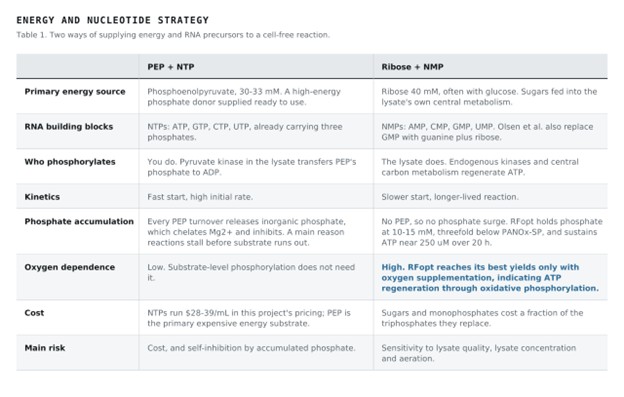
Explain how a PEP + NTP reaction formulation is different from a Ribose + NMP reaction formulation.
The difference is who does the phosphorylation: you, or the lysate.
In a PEP + NTP formulation the energy is bought pre-phosphorylated. Phosphoenolpyruvate is a high-energy phosphate donor, and pyruvate kinase already present in the lysate transfers its phosphate to ADP to regenerate ATP; the nucleotides arrive already as triphosphates. The reaction starts fast and reaches high initial rates. It carries two costs. The first is money: PEP and the triphosphates are among the most expensive components, with CTP, GTP and UTP priced at $28–39/mL in this project. The second is self-poisoning: every turnover of PEP releases inorganic phosphate, which accumulates, chelates magnesium and inhibits the reaction. This is why PANOx-SP reactions stop producing after a few hours rather than running out of substrate.
In a ribose + NMP formulation cheap precursors are supplied and the lysate’s own metabolism phosphorylates them. Endogenous kinases convert nucleoside monophosphates to triphosphates, and ribose feeds central carbon metabolism to regenerate ATP. Olsen et al. (2026) found that GMP could be replaced entirely by guanine plus ribose with no loss of yield, and UMP by its base plus ribose with some loss. With no PEP there is no phosphate surge: their optimised system holds phosphate at 10–15 mM, threefold lower than PANOx-SP, and sustains ATP near 250 µM across a 20-hour reaction.
The trade is speed and robustness against cost and longevity. PEP + NTP buys a fast start with expensive reagents and builds up its own inhibitor. Ribose + NMP is far cheaper and lasts longer, but it leans on the lysate’s intact metabolism, which makes it sensitive to lysate quality and concentration, and oxygen-dependent: Olsen’s optimised formulation reached its highest yields only with 100% oxygen supplementation, indicating that ATP regeneration runs through oxidative phosphorylation rather than substrate-level phosphorylation.
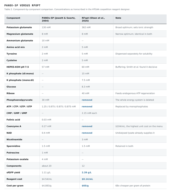
Choose two cell-free reaction compositions from the literature, compare and contrast the choice of reagents and the concentration of reagents.
I compared PANOx-SP (Jewett & Swartz, 2004) with RFopt (Olsen et al., 2026), and read both against the AI-designed formulations of Smith et al. (2026). Concentrations are taken as transcribed in the HTGAA coopetition reagent designer, so that the two are stated on the same basis.