I want to biomanufacture a custom-fitted bacterial-cellulose inner interface for lower-limb prosthetic sockets/ knee braces and potentially other wearable orthopedic devices. Instead of manufacturing a flat sheet of material and then cutting, joining, stretching, or thermoforming it around the residual limb, the material would be grown directly around a digitally fabricated 3D former derived from the user’s residual-limb scan.
The result would be a seamless, body-specific cellulose structure whose thickness, surface texture, porosity, and geometry could potentially be varied across different regions of the limb.
This interests me primarily from a product-design and human-factors perspective. The interface between the residual limb and prosthetic socket is extremely demanding: it experiences pressure, shear, friction, heat, and moisture. These conditions contribute to irritation, blisters, dermatitis, pressure injuries and other skin problems. Heat and perspiration are also significant problems; a literature review found that more than 53% of people with amputations in the included studies experienced heat and/or perspiration discomfort inside their prostheses. . Not just from comfort but even from a functionality point of view , one of the most notable problems related to knee braces is brace migration and that clubs in with interface pressure, thermal comfort, airflow etc .
Conventional silicon liners or EVA foam provide cushioning and suspension, but they can also trap heat and perspiration. Research on perforated liners suggests that deliberately controlling moisture pathways can improve residual-limb conditions. (PubMed)
Orthopedic wearables have a difficult design problem: the device needs to apply forces to the body, but the interface needs to remain comfortable while doing so.
For example, a knee brace may need to apply localized pressure to control movement or unload a joint, while simultaneously avoiding excessive pressure, friction, heat and discomfort.
Similarly, prosthetic sockets have to transfer loads between a rigid device and soft biological tissue.
That creates an interesting design opportunity for bacterial cellulose because I could potentially spatially engineer the material rather than treating the entire interface as one uniform piece..
Bacterial cellulose forms an interconnected nanofibrillar network and has high water-holding capacity, flexibility, microporosity, and useful mechanical properties. These characteristics have already led to extensive research into wound dressings and other biomedical applications.
My idea therefore is:
“Can I turn the geometry of a person’s body into the geometry of the biological manufacturing environment, so that bacteria grow the interface into its final form?”
I would use Komagataeibacter xylinus as the primary biological manufacturing chassis. K. xylinus is a bacterium well known for producing bacterial cellulose (BC) extracellularly. In a typical process, the bacteria are supplied with a carbon source such as glucose along with nutrients, water, and oxygen. They convert the carbon source through their metabolism and synthesize cellulose nanofibers outside the cells, which assemble into a dense, interconnected cellulose network.
At the simplest level:
Input
Sugar/glucose + nutrients + water + oxygen + K. xylinus
↓
Biological process
Bacteria metabolize the carbon source and synthesize cellulose → nanoscale cellulose fibrils assemble into a hydrated network
↓
Output
A hydrated bacterial-cellulose structure
BC is especially interesting because the material is extremely water-rich during production standard static fermentation can produce pellicles in which cellulose represents less than 2% of the wet mass.
For BioFit, I would modify the conventional production process by introducing a custom 3D cultivation former.
Instead of allowing the bacteria to produce a flat bacterial-cellulose pellicle, I would create a former based on a 3D scan of the user’s anatomy. The former would represent the desired inner surface of a knee-brace interface or prosthetic socket interface. The bacterial culture would then be introduced into a controlled cultivation chamber around the former, with the goal of allowing cellulose to accumulate and conform to its geometry.
The process would therefore become:
2.1. 3D scan of user
2.2. Parametric CAD model of interface
2.3. 3D-printed/custom moulded cultivation former
2.4. Inoculation with K. xylinus
2.5. Controlled cellulose growth
2.6. 3D bacterial-cellulose interface
2.7. Washing + purification + conditioning
2.8. Integration into prosthetic/orthotic device
The exact way that BC would grow on a complex 3D former is one of the major uncertainties in my proposal. Most established static BC production forms a pellicle at the air-liquid interface, and published studies commonly use relatively simple vessels and geometries. For example, one recent study cultured K. xylinus statically for seven days before harvesting the resulting pellicles.
Therefore, I am assuming that the cultivation environment can be redesigned to provide sufficient oxygen and nutrient access across the 3D former. This would need to be experimentally validated rather than assumed to work immediately.
Another assumption is that the BC would probably not be used as a completely standalone structural component. Depending on its mechanical and moisture-management properties, it could ultimately be combined with an elastomer, textile, foam, or other material to create a composite interface.
The biological system therefore produces the customized material architecture, while the final orthopedic product would still involve conventional mechanical/product-design components.
3. How would I use automation?
I would use automation primarily during the R&D and optimization stage, and then develop a different automated system for manufacturing.
Prototype/R&D: Opentrons liquid-handling robot
For early experiments, I would use an Opentrons OT-2 liquid-handling robot.
The OT-2 is a programmable benchtop liquid handler capable of performing repetitive liquid-transfer operations and can be controlled through protocols or Python. It can also work with modules such as temperature-control and HEPA systems.
I would use it to automate the preparation of many small bacterial-cellulose cultures with different conditions.Instead of manually preparing every experiment, the OT-2 could dispense the required volumes into standardized culture vessels.
The goal would therefore be to find a biological manufacturing condition that produces a material suitable for an orthopedic interface, rather than simply the highest possible cellulose yield.
The OT-2 is particularly appropriate for this prototyping stage because it is designed for repetitive liquid-handling workflows and supports programmable protocols.
Scaling beyond the prototype
The OT-2 would not be the machine I would use to manufacture 1,000 full-sized interfaces.
At manufacturing scale, I would envision a system consisting of:
3.1. Automated body scan 3.2. automated CAD/former generation
3.3. parallel bioreactors/cultivation chambers
3.4. environmental sensors
3.5. automated harvesting and washing
3.6. dimensional/material inspection
The important shift is that the automation changes from automating experiments to automating personalized manufacturing.
The cultivation chambers could operate in parallel, with each chamber containing a different patient’s customized former.
4. How much would I need to make?
For a meaningful first manufacturing target, I would define the scale as:
1,000 BioFit orthopedic interfaces
This could represent a mixture of knee-brace interfaces and prosthetic-socket interfaces.
For simplicity, I will assume that each interface requires approximately 50 g of dry bacterial cellulose.
This is an engineering assumption rather than a measured requirement. The actual amount would depend on the final geometry, thickness, whether BC is used alone or as a composite, and the mechanical requirements of the application.
5. How long would manufacturing take?
For a first back-of-the-envelope estimate, I’ll assume that my optimized shaped fermentation system produces approximately:
5 g dry BC/L
per production cycle.
This is deliberately an engineering assumption rather than a claim about a guaranteed industrial yield, because BC productivity varies substantially with strain, culture medium, reactor configuration and growth conditions. Production conditions and carbon sources are known to substantially influence BC manufacturing. (PubMed Central (PMC))
If I need:
50,000 g
then the total culture volume required is:
50,000 g5 g/L=10,000 L
So approximately 10,000 L of cumulative culture volume would be required.
Suppose each custom liner is grown in a roughly 10 L shaped cultivation chamber.
10 L×5 g/L=50 g
That corresponds conveniently to approximately one interface per reactor per cycle.
Now assume one growth cycle takes roughly 10 days, followed by approximately 2 days for harvesting, purification, conditioning and QC.
So:
12 days/production cycle
If a manufacturing facility operates 100 shaped reactors in parallel:
100 liners/cycle
For 1,000 liners:
1000100=10 cycles
Therefore:
10×12=120 days
or approximately:
4 months
for 1,000 custom interfaces with 100 parallel cultivation units.
Unlike producing one homogeneous chemical in a giant fermentation tank, every BioFit product has different geometry. Scaling therefore means creating a distributed array of individually shaped cultivation chambers, almost like biological 3D printers running simultaneously.
6. What don’t I know yet?
6.1 Can bacterial cellulose actually grow uniformly over a complex 3D form?
BC is commonly produced as a pellicle at an air–liquid interface. A residual-limb geometry has vertical surfaces, undercuts and varying curvature.
Can oxygen and nutrients be controlled so that cellulose grows with predictable thickness around an entire 3D former?
If not, the cultivation chamber itself needs redesigning.
6.2 Can the material survive the mechanical environment of a prosthesis?
A prosthetic interface experiences repeated compression, tension, shear, sweat and thousands of loading cycles.
BC has attractive mechanical properties, but that does not automatically mean that pure BC is suitable as a prosthetic liner.
I would need to measure:
compression recovery, shear resistance, fatigue life, wet/dry cycling, coefficient of friction and dimensional stability.
The outcome may be that BC should become a composite layer combined with an elastomer rather than replace silicone entirely.
6.3 Can moisture management actually be controlled?
High water-holding capacity sounds desirable, but in a prosthetic socket it could become either an advantage or a serious disadvantage.
If the material absorbs sweat and holds it against the skin, that could worsen maceration rather than solve it. Conversely, engineered pores or channels might transport moisture away from the skin.
So one of my main experiments would compare:
silicone liner vs. uniform BC vs. patterned/perforated BC
for moisture transport, temperature, friction and skin-interface conditions.
AI citation
AI client: ChatGPT, GPT-5.6 Luna, OpenAI. Accessed September 21, 2026.
Prompt:
“I am developing a biomanufacturing concept called BioFit — Grown-to-Shape Bacterial Cellulose Prosthetics/Orthotics Interface. The idea is to use Komagataeibacter xylinus to grow a custom bacterial-cellulose interface around a digitally fabricated 3D former derived from a user’s anatomy, for applications including prosthetic sockets and knee braces. Help me develop sections covering the living system, automation, manufacturing scale and time, and the major technical unknowns. Distinguish published information from engineering assumptions and provide sources for important quantitative claims.”
I created a Kernel repository and project folder for BioFit and used Kernel to assemble and inspect the genetic construct. I used Kernel’s sequence viewer, construct checker, codon optimization tool, sequence search/BLAST, and Biosecurity Sequence Scanner to design and quality-check the sequence.
Repository: Rosalea_BioFit
Construct: BioFit-Expression
Part 1 — Define the expression target
What am I trying to produce?
BioFit is a biomanufacturing concept for a custom bacterial-cellulose interface for prosthetic sockets, knee braces, and potentially other orthopedic wearables. The material would be grown around a digitally fabricated 3D former based on the user’s anatomy, with the goal of producing a body-specific cellulose interface rather than manufacturing a flat sheet and subsequently cutting and forming it.
The biological output is therefore bacterial cellulose, rather than a conventional recombinant protein product. In Komagataeibacter xylinus, cellulose is synthesized extracellularly from a carbon source and assembled into a hydrated nanofibrillar network
For this DNA design, I focused on the cellulose synthase machinery, particularly the catalytic cellulose synthase subunit BcsA.
Sequence
The main coding sequence analyzed was BcsA / cellulose synthase catalytic subunit [UDP-forming], corresponding to UniProt P19449.
The protein sequence used for the design was 754 amino acids long. The sequence corresponds to the catalytic subunit of bacterial cellulose synthase from Komagataeibacter xylinus. The P19449 annotation identifies it as the cellulose synthase catalytic subunit and the gene as bcsA.
BcsA catalyzes the polymerization of UDP-glucose into cellulose. The enzyme is therefore directly relevant to the biological manufacturing goal of BioFit
Host/chassis
The biological chassis selected in my original BioFit concept was Komagataeibacter xylinus because it is a bacterial cellulose-producing organism
However, Kernel currently records the expression host of the construct as Cricetulus griseus (Chinese hamster). This is an inconsistency in the current computational design. The construct also contains a bacterial promoter/RBS architecture. Therefore, the current construct should be considered a sequence-design prototype rather than a final host-matched expression design.
A next iteration would need to align the Kernel expression-host setting, promoter, translation-initiation element, and backbone with the intended biological chassis.
Where does the product need to go?
The final bacterial cellulose is intended to be produced extracellularly by the cellulose-producing chassis. The goal of BioFit is ultimately to grow the cellulose structure around a custom 3D former rather than simply express and purify BcsA as an isolated protein. The spatial manufacturing concept therefore depends on extracellular cellulose production by the bacterial chassis.
The resulting construct was approximately 9.3 kb in Kernel.
The overall architecture is:
Ptrc2 → RBS → BcsA → BcsB → BcsC → BcsD → BBa_B0015
Design rationale
The construct was designed around the cellulose synthase system rather than treating BcsA as an isolated protein because BioFit requires cellulose production as the final biological output.
BcsA is particularly important because it is the catalytic subunit responsible for polymerizing UDP-glucose into cellulose.
The additional Bcs components were included to represent the broader cellulose-synthesis machinery rather than relying on the catalytic subunit alone.
INSERT IMG
Part 3 — Assemble the construct
The construct was assembled in Kernel in the following 5′→3′ order:
Ptrc2 → RBS → BCSA1_KOMXY → BCSB1_KOMXY → BCSC1_KOMXY → BCSD1_KOMXY → BBa_B0015
The resulting construct is approximately 9,325 bp according to Kernel.
Kernel’s construct viewer was used to inspect the sequence and confirm the order and orientation of the components. The assignment specifically requires checking the reading frame, start/stop codons, internal stops, and orientation.
Construct checker
Kernel initially returned several warnings, including:
unequal promoter/Kozak/UTR counts,
fewer polyA elements than promoters,
several parts marked as “not recommended.”
These warnings are important because they indicate that the construct is not perfectly matched to the expression context currently selected in Kernel.
In particular, the construct uses a Ptrc2 promoter and RBS, which are characteristic of a bacterial expression architecture, while Kernel lists Cricetulus griseus as the expression host. Therefore, the warnings should not simply be ignored; they identify a host/architecture mismatch that would need to be resolved in a future design iteration.
Part 4 — Optimize and quality-check
4.1 Codon optimization
I used Kernel’s Codon Optimizer on the BcsA protein sequence.
Input
Input type: Amino acid
Protein: BcsA / cellulose synthase catalytic subunit
Length: 754 aa
Expression organism selected in Kernel: Cricetulus griseus (Chinese hamster)
Algorithm: Simple v0.3
Restriction-enzyme constraints: None specified
Motif constraints: None specified
The optimizer converted the amino-acid sequence into a DNA coding sequence appropriate to the selected expression organism.
Why codon optimization matters
Different organisms use synonymous codons at different frequencies. Although synonymous codons encode the same amino acid, their frequencies can affect how efficiently a heterologous coding sequence is translated in a particular host.
Therefore, codon optimization changes the DNA sequence while preserving the intended protein sequence. In this design, the optimization was used to produce a host-oriented DNA version of BcsA rather than simply copying the native bacterial coding sequence.
The optimized sequence began with ATG and included a terminal TAA stop codon.
Constraints
No additional restriction-site or motif constraints were entered in the Kernel optimization interface. Therefore, the main design change was codon usage for the selected host.
Important limitation: because the intended BioFit chassis from HW1 is K. xylinus, optimization for C. griseus is not necessarily the final biologically appropriate choice. A future version should optimize the sequence for the actual production chassis if the construct is intended for expression in K. xylinus.
[Insert Codon Optimizer screenshot here.]
4.2 Sequence search / BLAST
I used protein BLAST to determine whether the sequence corresponded to the expected cellulose synthase protein.
The query was:
UniProt P19449
The BLAST result had:
Query length: 754 aa
Top matches: cellulose synthase catalytic subunits
Query coverage: 100%
E-value: 0.0
Top reported identity: approximately 96.55%
Top organism: Komagataeibacter xylinus
The results strongly supported that the sequence is a cellulose synthase catalytic subunit, rather than an unrelated or novel protein. The BLAST matches were also consistent with the UniProt P19449 annotation for BcsA from K. xylinus. Independent database results likewise identify P19449 as a UDP-forming cellulose synthase catalytic subunit from K. xylinus.
This was an important quality-control step because it confirmed that the protein sequence used for the BioFit design matched the intended biological function.
[Insert BLAST screenshot here.]
4.3 Biosecurity sequence scan
I also ran Kernel’s Biosecurity Sequence Scanner on the optimized DNA sequence.
Result
No flagged sequences detected.
The scanner did not identify any sequences in the input that were flagged by its biosecurity screening database.
This provides a computational safety check on the designed sequence. It does not demonstrate that the biological system is experimentally safe or that the entire design is risk-free; it only reports the outcome of this particular sequence-screening step.
[Insert screenshot showing “No flagged sequences detected” here.]
Part 5 — From design to build
How would I build the construct?
The final construct is approximately 9.3 kb, making a fragmented synthetic-DNA approach attractive for a prototype.
I would use commercially synthesized DNA fragments followed by sequence-verified assembly, rather than attempting to construct the entire sequence from a large pool of short oligos manually.
A practical conceptual workflow would be:
Design → synthesize sequence fragments → sequence/QC fragments → assemble overlapping fragments → verify final construct
For assembly, Gibson assembly is a reasonable approach because it can join overlapping DNA fragments in a single isothermal reaction using exonuclease, polymerase and ligase activities. Gibson et al. demonstrated assembly of multiple overlapping DNA molecules into much larger constructs.
For a ~9.3 kb construct containing multiple functional elements, dividing the construct into several manageable synthetic fragments would also reduce the difficulty of obtaining one completely error-free long molecule.
What does DNA synthesis constrain?
Synthetic DNA is not perfectly error-free. Errors can arise during oligonucleotide synthesis and subsequent amplification/assembly, and the probability of obtaining an error-free product becomes more challenging as sequence length increases.
Carr et al. demonstrated that error correction can substantially reduce errors in de novo DNA synthesis and showed the importance of error correction for longer synthetic targets. Their work reported an improvement to approximately one error per 10,000 bp after error depletion.
Week 3 HW: cell free systems
Objective
The objective of this assignment was to design novel cell-free protein synthesis (CFPS) reaction compositions for three target proteins — sfGFP, PETase, and Reteplase — with the goal of reducing the cost per gram of functional protein.
CFPS uses cell lysate containing the machinery required for transcription and translation, combined with DNA, amino acids, nucleotides, energy sources, salts, cofactors, and other components. Since individual reaction components can be adjusted independently, CFPS provides a flexible platform for optimizing protein production and cost. The three proteins were selected because they represent increasing levels of folding difficulty: sfGFP has no disulfide bonds, PETase has one disulfide bond, and Reteplase has nine disulfide bonds.
A. COMPARE CELL-FREE REACTION COMPOSITIONS (20 minutes)
Why does the concentration of potassium glutamate and magnesium glutamate differ between compositions? Which is more sensitive?
Potassium glutamate (K-Glu) and magnesium glutamate (Mg-Glu) both contribute to the ionic environment required for efficient transcription and translation.
However, they do not play identical roles. K-Glu primarily helps establish the overall ionic strength of the reaction, while Mg²⁺ has a more sensitive role in processes involving nucleic acids, ribosomes, and ATP/NTP interactions.
Therefore, the concentrations of K-Glu and Mg-Glu differ between optimized formulations because the two ions affect the CFPS system differently. Mg-Glu is generally the more sensitive parameter, meaning relatively small changes in Mg²⁺ concentration can significantly affect reaction performance.
Explain how a PEP+NTP reaction formulation is different from a Ribose+NMP reaction formulation.
A PEP + NTP formulation uses phosphoenolpyruvate (PEP) as an energy-regeneration substrate and nucleotide triphosphates (ATP, CTP, GTP and UTP) as the building blocks for transcription.
A Ribose + NMP formulation instead uses ribose together with less expensive nucleotide monophosphates (AMP, CMP, GMP and UMP).
The major difference is therefore both how energy is regenerated and how nucleotides are supplied.
The Ribose + NMP approach is particularly interesting for cost optimization because NTPs such as CTP, GTP and UTP are relatively expensive. Prior work has shown that partial replacement of NTPs with cheaper NMPs can reduce CFPS cost.
Choose two cell-free reaction compositions from the literature, compare and contrast the choice of reagents and the concentration of reagents.
or this comparison, I considered the PANOx-SP formulation and the later cost-optimized formulation described in the assignment.
The PANOx-SP approach uses a conventional energy-regeneration system based around PEP and NTPs, whereas newer cost-optimized approaches investigate ways of reducing expensive reagents while maintaining protein production.
Important cost-optimization strategies include:
Improving pH buffering
Partially replacing NTPs with NMPs
Using small amounts of spermidine
Reducing unnecessary expensive cofactors where possible
Part B — Designing New CFPS Compositions
The CFPS reaction has a fixed total volume of 20 µL. The fixed components are:
Lysate: 5,000 nL
DNA: 2,000 nL
Base buffer: 2,000 nL
This leaves 11,000 nL for variable reagents, with unused volume filled with nuclease-free water. Reagent volumes must be specified in 25 nL increments
3.1 sfGFP Design
Design goal
sfGFP is the least challenging of the three proteins because it does not require disulfide-bond formation. Its fluorescence provides a direct measurement of correctly folded functional protein. I therefore focused primarily on cost reduction while maintaining a stable reducing CFPS environment.
Reagent
Reference
My design
Rationale
K-Glu
280 mM
300 mM
Explore a moderate ionic-strength adjustment
Mg-Glu
8.22 mM
7.6 mM
Explore a slightly lower Mg²⁺ concentration
Amino acids
2 mM
2 mM
Maintained baseline
HEPES
57.5 mM
57.5 mM
Maintained pH buffering
PEP
30 mM
30 mM
Maintained energy regeneration
ATP
1.25 mM
1.25 mM
Maintained
CTP
0.875 mM
0.75 mM
Reduce expensive NTP usage
GTP
0.875 mM
0.75 mM
Reduce expensive NTP usage
UTP
0.875 mM
0.75 mM
Reduce expensive NTP usage
Spermidine
—
1.88 mM
Explore cost/yield optimization
The major cost-oriented change was reducing CTP, GTP and UTP while introducing a small amount of spermidine. This follows the general cost-optimization strategy described in the assignment, where partial NTP replacement and spermidine were associated with reduced cost per gram.
3.2 PETase Design
PETase is more challenging than sfGFP because TfCut2 contains one disulfide bond and must form the correct structure to be enzymatically active
Because PETase remains compatible with reducing CFPS conditions, I retained the basic PEP-based formulation and focused on reducing the cost of nucleotide components.
Reagent
Reference
My design
Rationale
K-Glu
200 mM
200 mM
Maintained
Mg-Glu
10.1 mM
10.1 mM
Maintained
NH4-Glu
10 mM
10 mM
Maintained
Amino acids
2 mM
2 mM
Maintained
HEPES
57.5 mM
57.5 mM
Maintained
PEP
30 mM
30 mM
Maintained
ATP
1.25 mM
1.25 mM
Maintained
CTP
0.875 mM
0.75 mM
Reduce NTP cost
GTP
0.875 mM
0.75 mM
Reduce NTP cost
UTP
0.875 mM
0.75 mM
Reduce NTP cost
Spermidine
—
1.88 mM
Explore optimization
deliberately made fewer changes to PETase than to sfGFP because the protein has an additional folding requirement. The intention was to explore cost reduction without substantially changing the established reaction environment.
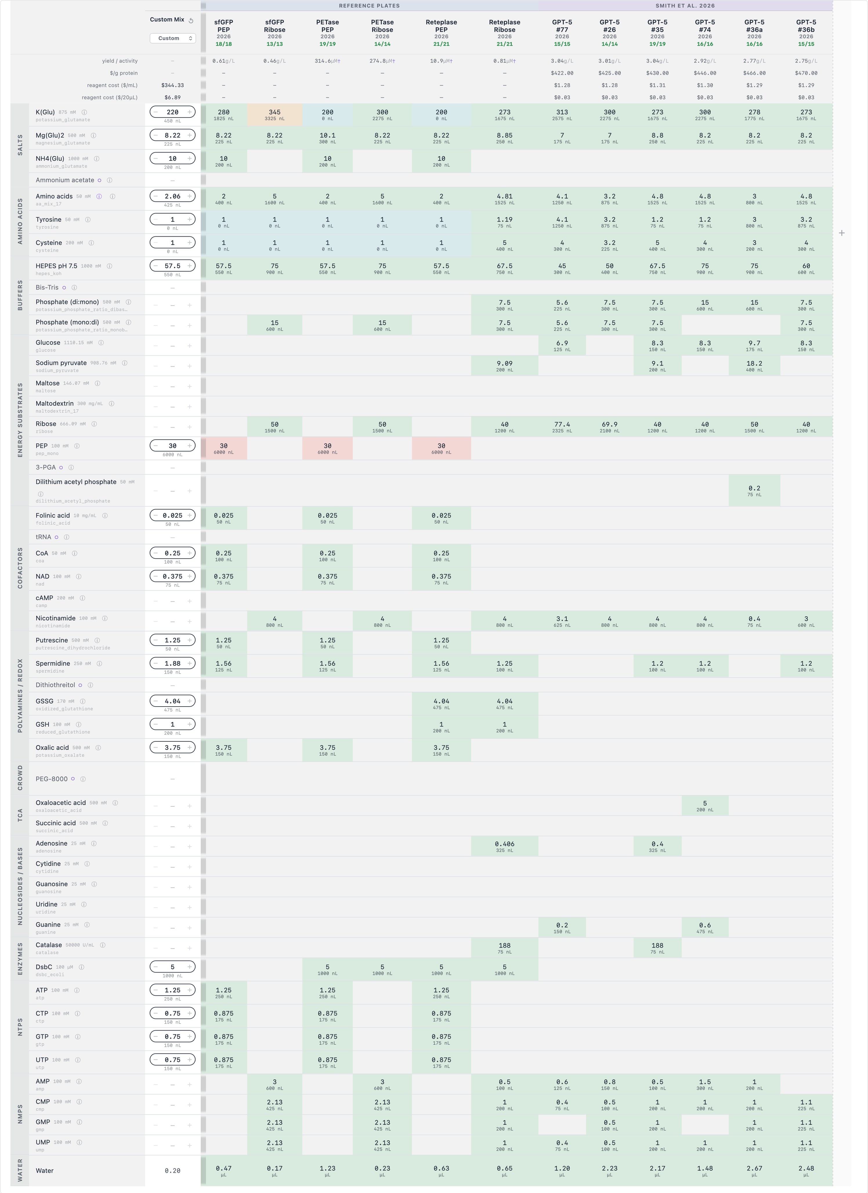
3.3 Reteplase Design
Reteplase presented the greatest design challenge because it contains nine disulfide bonds, all of which must form correctly for the protein to become functional.
Unlike sfGFP and PETase, Reteplase therefore requires an oxidizing CFPS formulation. The assignment specifically describes the use of a modified lysate, GSSG/GSH redox buffering, DsbC, and a Δgor lysate.
For this reason, I preserved the key disulfide-folding components rather than removing them purely for cost reduction.
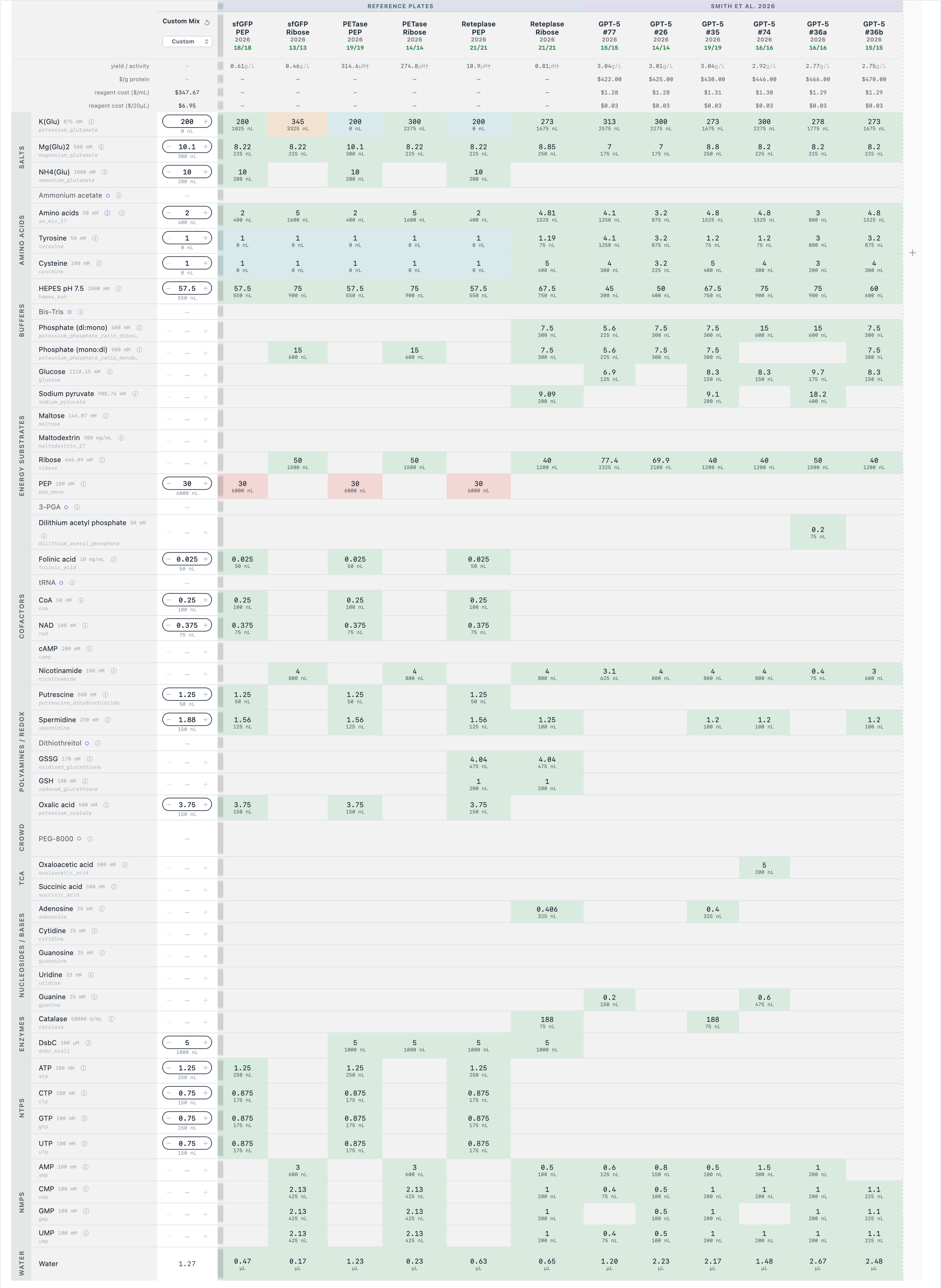
Reagent
Reference
My design
Rationale
K-Glu
200 mM
220 mM
Explore ionic environment
Mg-Glu
8.22 mM
8.22 mM
Maintained
NH4-Glu
10 mM
10 mM
Maintained
Amino acids
2 mM
2.06 mM
Small adjustment within designer constraints
HEPES
57.5 mM
57.5 mM
Maintained
PEP
30 mM
30 mM
Maintained
ATP
1.25 mM
1.25 mM
Maintained
CTP
0.875 mM
0.75 mM
Reduce NTP cost
GTP
0.875 mM
0.75 mM
Reduce NTP cost
UTP
0.875 mM
0.75 mM
Reduce NTP cost
GSSG
4.04 mM
4.04 mM
Preserved redox environment
GSH
1 mM
1 mM
Preserved redox environment
DsbC
5 mM
5 mM
Preserved folding assistance
Spermidine
—
1.88 mM
Explore optimization
4. Community Reagent — FkpA
For the Community Reagents section, I selected FkpA.
FkpA is an E. coli chaperone with peptidyl-prolyl isomerase activity that can assist protein folding. I selected it because Reteplase has nine disulfide bonds and therefore represents the most demanding folding problem among the three targets.
The reasoning was to add a reagent that addresses functional protein folding, rather than simply increasing protein expression.
FkpA is particularly interesting because it can complement DsbC, which is already present in the Reteplase formulation. The assignment identifies DsbC as a folding helper that rearranges incorrectly paired disulfide bonds
Research supporting the choice
Groff et al. demonstrated that FkpA and DsbC can act as positive effectors of difficult disulfide-containing protein folding and assembly.
Reference:
Groff, M. et al. (2014). Engineering toward a bacterial “endoplasmic reticulum” for the rapid expression of immunoglobulin proteins.
. Design Strategy
Across all three proteins, my overall strategy was:
Start from the closest reference formulation →
Identify expensive or potentially adjustable reagents →
Make small changes rather than changing the entire formulation →
Preserve protein-specific folding requirements →
Prioritize functional protein rather than total protein expression.
This was particularly important for Reteplase. Since activity depends on correct formation of its nine disulfide bonds, simply increasing total expression would not necessarily improve functional yield. The assignment similarly emphasizes that different target proteins can require different reaction conditions.
6. AI-Assisted Design
prompts:
“Explain the difference between potassium glutamate and magnesium glutamate in CFPS.”
“Explain the difference between PEP + NTP and Ribose + NMP formulations.”
“Help me design a cost-conscious CFPS formulation for sfGFP using the reference formulation.”
“Help me reason about which reagents should be preserved for Reteplase and why.”
“Explain why DsbC, GSSG and GSH are important for Reteplase.”
“Help me evaluate FkpA as a potential community reagent for improving Reteplase folding.”